Interference Colors
The wave property of light is evidenced by the phenomenon of
interference. Because light interferes with itself we can
measure its wavelength with simple experiments. Any interference
experiment on light will demonstrate its "waviness." Together with
particle experiments demonstrating the infinitessimal particle nature
of photons, these experiments illustrate the mystery of what light
really is.
Waves and Interference
Waves contain positive and negative parts.
At an one moment over the surface of Lake Erie, half of the water is
higher than normal (positive) and half is lower than normal (negative).
In an electromagnetic wave, half the time the electric field points in
one direction and half the time it points in the opposite direction.
Superposition
Unlike most particles we are familiar with, more than one wave can
occupy any one volume at the same time.
Waves run through each other without one wave "knowing" about the
other.
Imagine a long wavelength wave with a short wavelength wave on its back.
As far as the long wave is concerned, it is simply lifting the short
wave up and down.
As far as the short wave is concerned, the long wave has simply altered
the normal "zero-point" of the wave.
At any one point the total electric field is the sum of the
local electric fields of all the waves present.
Physicists call this summing superposition.
On this page from the University of Colorado
is an applet which demonstrates superposition.
Two waves and their sum are presented.
The reader can change the wavelength and amplitude of each wave independently
by moving the dots on the amplitude/wavelength chart with the mouse.
This diagram is an annotated frame capture from the applet.

Interference
Paradoxically, the "not knowing about the other" can lead to interference.
Interference occurs when two rays with the same wavelength
end up traveling together.
If the waves are shifted so the positive parts of one wave are
coincident with the positive parts of the other wave, the amplitudes add.
This condition is called constructive interference.
If the positive parts of one wave are coincident with the negative parts
of the other wave, the amplitudes cancel and result in no wave.
This condition is called destructive" interference.
The energy and momentum of the "destroyed" waves must have gone somewhere else.
Phase
How much shift there is between the positive/negative parts of each wave
relative to the wavelength is called the phase shift.
The phase of a wave is where you are on the wave relative to the
zero-crossing from negative to positive.
Phase is measured in units of angle.
One wavelength is 360° of phase.
The positive parts of a wave occupy the first 180° of phase and the
negative parts occupy the last 180° of phase.
A phase shift of 0° between two identical waves is completely
constructive.
A phase shift of 180° between two identical waves is completely
destructive.
Other shifts may be partially constructive or partially destructive.
With the above applet one can explore phase shifts by click-dragging
on one or the other wave.
Try doing that with the amplitudes and wavelengths equal.
One might ask how one makes two waves of equal wavelength travel in
the same direction at the same place and time.
The next sections describe such circumstances.
Young's double slit experiment
In 1801 Thomas Young devised an experiment which showed unequivocally the
waviness of light through its interference effects.
Imagine a monochromatic (light of only one wavelength) beam striking
a single slit in a barrier as shown below.
If the slit is relatively narrow compared to the wavelength, the
wave passing through will diffract
and spread out away from the opening.
Now let's open another slit nearby.
The diffracting wave from that slit will overlap (superpose on) the wave from
the first slit.

If we place a screen at the right edge of the diagram, the screen will
be bright where constructively interfering waves strike it and dark
where waves have been eliminated by destructive interference.
Such destructive interference occurs along the grayish "rays" leading out
from the slits.
Here is are still diagrams illustrating how the interference pattern
comes about.
 |
 |
| Destructive | Constructive |
In both diagrams, the 'green' phase of the wave is passing through the slit.
Everywhere that the composite wave is bright green is an integer number
of wavelengths from both slits.
In such places the green from one slit constructively interferes with the
green from the other slit (positive plus positive).
Everywhere that the composite wave is bright magenta is an integer number
plus 1/2 wave from both slits.
In such places the magenta from one slit constructively interferes with the
magenta from the other slit (negative plus negative).
Everywhere that the composite wave is gray is an integer number of
waves from one slit, but an integer number plus 1/2 wave from
the other slit.
In this last case, the green from one slit destructively interferes with the
magenta from the other slit (positive plus negative).
The pattern of light and dark seen on a screen behind two slits is called
a fringe pattern, and is a sure sign of interference and waves.
This demonstration was Young's achievement.
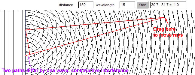
Here is an applet which allows you to
adjust the wavelength of the incoming light and the slit separation.
After opening the link, click the 'start' button to open the applet window.
I suggest widening the applet after it opens by dragging the edges.
You may adjust the slit separation by dragging on a slit.
You may drag the point of intersection of the rays from each slit to various
places on the pattern and see how many wavelengths one path is longer
than the other.
Here is a frame capture of what you will see.
An aside on the photon nature of light
Clearly a wave has to go through both slits in order to interfere with
itself and make a fringe pattern on a distant screen.
Waves can do that because they are non-local phenenomena, meaning
they are not confined to a single location.
Particles, on the other hand, are local phenomena.
If we dim the entering light beam to lower and lower intensity,
we will find that the energy striking the slits becomes intermittent,
which is just another way of saying localized.
A detector put behind each slit will record which slit a photon
passes through.
When asked, photons must 'choose' which slit to go through; they cannot
split and go through both.
Photons are elementary particles of zero size.
However, if we don't ask the photon which slit it went through,
something very strange happens.
It interferes with itself.
If we place an array of small detectors well behind the slits we will
still find only intermittent detections in each detector, one at a time.
Photons are always detected as local particles.
But, over time, a fringe pattern emerges.
Photons never strike a detector located in a position of
destructive interference.
How do the photons know where they should go?
Did they go through both slits when we weren't looking?
If we try to detect which slit they go through on the way to the
screen, the fringe pattern disappears.
Cheeky little devils.
The diffraction grating
A diffraction grating is a sheet of film (transmission grating)
or a mirror (reflection grating) with a series straight scratches spaced only
a few wavelengths apart.
Each scratch acts as a source of diffraction, sending out cylindrical
wavefronts from an incoming beam.
As with two slits, the overlapping waves produce an interference
fringe pattern.
But, far away from the grating, only a few ray directions survive.
Imagine white (many wavelength) light striking a transmission grating.
The transmitted waves emerge in all directions from each scratch.
Rays coming out at just the right angle so the ray from each scratch is just
one wavelength ahead of its neighbor ray will be constructive for all
scratches.
The diagram below illustrates violet and red rays.
The red rays come out at a larger angle because the short side
of the little triangle formed by the grating, a wavelength, and a
wavefront is longer for red rays than it is for violet rays.
For any other ray direction, some pair of scratches (separated
by, say, 23 scratches) will be nearly, if not completely, destructive
to each other.
Then, every such sequential pair will eliminate themselves.
No light will propagate in this other direction.
The result is that only rays which have an integral number of wavelengths
difference between adjacent scratches will emerge from the grating.
A grating separates wavelengths by direction as a prism does, except
the order is reversed: red is bent more than blue-violet.
We can use the angle of emergence to determine the wavelength of
any color of the rainbow.
Below is a diagram of green light emerging from a grating in only one
direction and making a dot on a distant screen.
The grating is drawn at an expanded scale both in the main figure and the
enlargement view.
The two triangles with sides A D S and a d w
are similar, that is they have the same proportional shape.
We may write w / d = S / D.
Solving for the wavelength w gives
w = S (d / D).
So if we know the grating spacing d and measure the two distances
S and D, we can calculate w.
A recording CD makes a good reflection grating.
When white light strikes the surface, it scatters off in all directions.
The spiral groove on the disc provides the opportunity for interference.
Here is an illustration of the eye's view of a reflection grating.
An observer sees the red reflection in a different location
from the violet reflection.
White light spreads out into a spectrum of reflections.
Spectrally reflecting decorative stickers work the same way.
Thin films
Another way to get two light rays to superpose is by partial
reflection from both sides of a thin film.
In the reflection
module we mentioned that transparent materials like glass
and water reflect a few percent of normal incidence radiation.
The important feature of such reflection is the change in index
of refraction.
If a wave reflects off a material with a higher index of refraction
(for example, light in air reflecting off water) its phase is
inverted.
That is, the part of the wave that was positive comes out negative
and vice versa.
If a wave reflects off a material with a lower index of refraction
(for example, light in water reflecting off air) its phase is not
inverted.
Here is what happens when light passes through a film of soap exactly
1.5 / 2 'green' wavelengths thick.
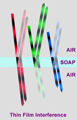
Consider the green wave first.
Five percent reflects off the top surface with a phase reversal.
notice that there are two green portions in a row, before and after
the reflection.
Ninety-five percent continues into the soap.
Another five percent reflects off the bottom surface without a
phase reversal.
After traveling back through the film for a total of 1.5 wavelengths
in the soap, 95% of this beam exits back into the upper air.
No phase reversal occurs on transmitted light.
The new upper beam is now in phase with the initially
reflected beam.
The two waves of nearly equal strength constructively interfere.
The wave that reflects inside at the top surface heads downward
and cancels a small fraction of the beam that otherwise would have
emerged out the bottom.
Now consider the red wave.
The red wavelength is not quite 1.5 times longer than the green wave,
so it spends just about one full wave inside the film traveling back
and forth.
On emerging from the top side, it destructively cancels the
first reflected wave.
The twice reflected wave coming out the bottom is in phase with
the original transmitted beam.
Finally consider the blue beam.
It spends just about two full waves inside the film and has a similar
interference behavior as the red wave.
Thus, from a film of this thickness, the upward reflection is greenish
and the tranmission is missing green, making it magenta.
If the film has a different thickness, different wavelengths will
be reflected while others will be transmitted.
Varying thickness contributes to the banded colors one often sees
when thin films are involved.
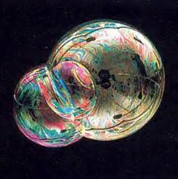
Soap bubbles
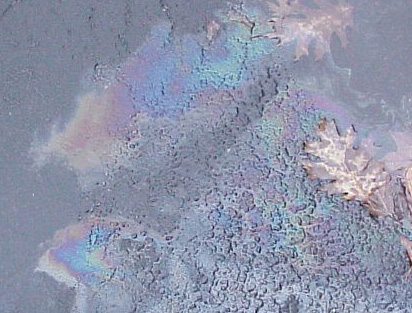
An oil spill
Some camera lenses have thin coatings on them specifically designed
to reflect ultraviolet sunlight by thin-film interference.
Photographic film is sensitive to UV radiation.
These lenses look bluish because they also reflect some short-wave
visible light.
Antique glass develops oxidation layers which also act as thin films.
Some artists apply thin metal oxide layers to glass or ceramic glazes
to give interference coloring.
Art glass in Nitschke Hall and the Corpus Christi Church is coated with
metalic films.
Jack-in-the-Pulpit Vase by
Louis Comfort Tiffany
Iridescence
The word iridescence derives from the Greek iris, meaning
rainbow, and Latin -escens, meaning the beginning of or an incomplete
action.
We will see lots of other -escences dealing with light.
Iridescence is commonly considered to mean a visual quality that
changes color depending on the orientation of the viewing direction.
Anything that displays iridescence does so through interference.
We have seen that gratings (for example, the recording grooves on a CD)
send out different wavelengths in different directions.
As a result, they look different colors when seen from different
directions.
Tilting the grating will shift the colors.
Thin films are also iridescent.
As shown in the figure below, the path length through the
film changes with angle, so the phase shift between the reflections off the
two surfaces will will change with angle.
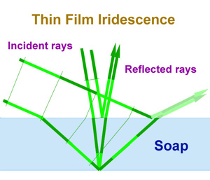
The iridescence of thin films is a dead giveaway of the interference
process.
If an object is not iridescent, its color is most likely due to
selective absorption and/or scattering of wavelengths rather than interference.
Many objects in nature are iridescent.
Opals and peacock feathers produce color by grating structures.
Pearls and butterfly scales produce color by thin film structures.
Some of these cases are decribed in more detail in the
InDepth Material:
Interference in nature.
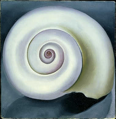
In her painting above, O'Keeffe successfully reproduces the impression of
iridescence without actually using iridescent paint.
Iridescent automobile paints
If O'Keeffe were alive today, she may have been entranced by the new
auto paints that are iridescent.
One manufacturer uses thin flakes of aluminum coated with layers of
different metal oxides to create local thin-film interference.
These flakes are then incorporated into a colored dye matrix of more
standard paint material.
Summary:
The wave property of light is evidenced by the phenomenon of
interference. Because light interferes with itself we can
measure its wavelength with simple experiments. Any interference
experiment on light will demonstrate its "waviness." Together with
particle experiments demonstrating the infinitessimal particle nature
of photons, these experiments illustrate the mystery of what light
really is.
Waves "ride" on top of each other without one wave "knowing" about the
other.
Physicists call this "riding" superposition.
Paradoxically, the "non-knowing" can lead to interference.
Interference occurs when two rays with the same wavelength
end up traveling together.
If the waves are shifted so the "peaks" of one wave are coincident with
the peaks of the other wave, the amplitudes add. This condition
is called "constructive" interference.
If the peaks of one wave are coincident with the "valleys" of the other
wave, the amplitudes cancel and result in no wave. This condition is
called "destructive" interference.
The energy and momentum of the "destroyed" waves must go somewhere else.
How much shift there is between the peaks relative to the wavelength is
called the phase shift. The phase of a wave is where
you are on the wave relative to the peaks and valleys.
Light waves can be "split" and recombined with phase shifts
by small slits, scattering gratings, and thin films which partially
reflect from each surface.
This property of light is conceptually inconsistent with
experiments which reveal the particle nature of light.
Be able to understand the way these phase shifts are produced, and the
pattern of interference that results.
Objects producing color by interference effects display iridescence,
a change in color when viewed at a different angle.
Sample Questions
Reminder: understanding the "big picture" of interference will answer
all of the below questions, without resorting to memorizing individual
answers.
What is constructive interference? destructive interference?
When light with one wavelength (e.g. laser light) goes through slits,
how do we determine what angle of emergence will be constructive?
destructive?
When light with many wavelengths goes through slits, what will be the
order of "colors" on a distant screen?
How is diffraction involved in slit or grating interference?
How can we use the color pattern to determine the wavelengths of light?
How does a thin film (oil slick, soap bubble) produce colors?
Why does interference result in iridescence?
Be able to identify a variety of natural optical phenomena resulting from
both diffraction-grating interference and thin-film interference.
What accounts for the iridescence in recently available automobile paints?
Why is interference inconsistent with a particle interpretation of light?