Q3Radiant Editor Manual
Based on Version 192
By Paul Jaquays
With additional contributions by Astrocreep, Christian
Antkow,
EutecTic, Inolen, Mr. Elusive, Maddog, Martin Ka’ai
Cluney,
Robert A. Duffy, Small Pile of Gibs, Suicide20, and The
Dog!
Special thanks go out to the members of the Quake3world
Editing forum.
Your questions prompted many of the sections in this
manual.
Q3Radiant Editor Manual.................................................................................................................................................................................... 1
Table of Contents........................................................................................................................................ 2
Preface................................................................................................................................................................. 6
Introduction................................................................................................ 6
Minimum System
Requirements................................................................................................................................................................................ 6
Minimum System.......................................................................................................................................... 6
Recommended System.............................................................................................................................. 7
What Doesn’t Work (well) … and How to fix it..................................................................... 7
Installation & Set Up................................................................................................................................. 8
Installing the editor.............................................................................................................................. 8
Setting up Paths.......................................................................................................................................... 8
Improving Performance......................................................................................................................... 8
Setting up Preferences............................................................................................................................ 8
The Project File.......................................................................................................................................... 16
Setting up the Windows....................................................................................................................... 18
Entities and Assets.................................................................................................................................... 21
What are Entities?.................................................................................................................................. 21
What are Assets?..................................................................................................................................... 21
Creating New Assets.............................................................................................................................. 22
Making the .pk3 File................................................................................................................................. 24
Map Building Basics.................................................................................................................................. 26
Moving Around.......................................................................................................................................... 26
Basic Construction Tutorial.......................................................................................................... 27
Tools 1: Selecting and deselecting............................................................................................... 30
The Component Handling Tools...................................................................................................... 30
Group Component Selections............................................................................................................ 31
Copying, Pasting, Cloning, Deleting and Prefabs................................................................. 32
Working with Regions........................................................................................................................... 33
Tools 2: Working with Brushes....................................................................................................... 35
Geometry Brush Handling Tools.................................................................................................... 35
Brush Menu Commands........................................................................................................................ 41
Moving Selected Brushes..................................................................................................................... 43
Efficient Brush Building Techniques............................................................................................ 44
Tools 3: Working with Curve Patches........................................................................................ 46
Curve Menu Commands......................................................................................................................... 46
Patch Tool Bar.......................................................................................................................................... 50
Moving Patches......................................................................................................................................... 52
Tools 4: Working with Textures..................................................................................................... 54
Brush Primitives: A New Format..................................................................................................... 54
Texture Creation: Making new Assets....................................................................................... 54
Texture Manipulation: Shader Overview................................................................................ 54
Texture Application: Texture Handling Tools..................................................................... 55
Using Interactive Textures............................................................................................................... 62
Tools 5: Working with Entities........................................................................................................ 67
The Entity Window.................................................................................................................................. 67
Entity Handling Tools.......................................................................................................................... 69
Tools 6: Lights & Lighting.................................................................................................................... 72
Tools 7: Miscellaneous Commands............................................................................................... 74
Feedback & Read-outs........................................................................................................................... 74
Viewing, Seeing, Not seeing, and Hiding........................................................................................ 75
File Management Commands........................................................................................................... 82
Projects and Preferences................................................................................................................... 83
Miscellaneous Commands................................................................................................................. 83
Opening Menus from the Keyboard............................................................................................... 84
Tools 8: Compiling Maps........................................................................................................................ 85
Tools 9: Debugging Maps........................................................................................................................ 87
The Editor’s Debug Tools..................................................................................................................... 87
In-game Debug tools............................................................................................................................... 89
Curves, Caulk, T-Junctions and Cracks..................................................................................... 92
A Debug Config............................................................................................................................................ 94
Appendix A: Glossary of Terms......................................................................................................... 96
Appendix B: Entity Descriptions....................................................................................................... 98
Basic Key information.......................................................................................................................... 98
Ammo_* Entities........................................................................................................................................ 98
Func_* Entities......................................................................................................................................... 100
Holdable_* Entities.............................................................................................................................. 107
Info_* Entities.......................................................................................................................................... 108
Item_* Entities.......................................................................................................................................... 110
Light Entity................................................................................................................................................ 114
Path_* Entities......................................................................................................................................... 117
Shooter_* Entities................................................................................................................................. 118
Target_* Entities.................................................................................................................................... 118
Team_* Entities........................................................................................................................................ 125
Trigger_* Entities................................................................................................................................... 126
Weapon Entities...................................................................................................................................... 128
Worldspawn Entity............................................................................................................................. 130
Appendix C: Bot Navigation Files................................................................................................... 132
Introduction............................................................................................................................................ 132
Description................................................................................................................................................. 132
Installation............................................................................................................................................. 132
Usage.............................................................................................................................................................. 132
Updating the Entity Lump................................................................................................................. 133
Leaks.............................................................................................................................................................. 134
Useful Map Information................................................................................................................... 134
Optimizing a Map for bspc Compiling......................................................................................... 135
Entities & the Navigation File........................................................................................................ 136
Testing .AAS files.................................................................................................................................... 138
Version Changes...................................................................................................................................... 139
Appendix D: Tricks, Tips, and Tutorials..................................................................................... 141
Making the death fall sound…................................................................................................... 141
Making a Mirror …................................................................................................................................ 141
Making a Jump Pad................................................................................................................................ 141
Making a Launch Pad.......................................................................................................................... 142
Making a “Rocket Arena” style map......................................................................................... 142
Making an Environment Box …..................................................................................................... 142
Making a Shooter.................................................................................................................................. 143
Appendix E: Online Resources........................................................................................................... 145
News about the Editor....................................................................................................................... 145
Editing Tutorials................................................................................................................................... 145
Editing Tools............................................................................................................................................. 146
Prefab Sources......................................................................................................................................... 146
Texture Sources...................................................................................................................................... 147
Map Object Model Sources............................................................................................................... 148
Sounds........................................................................................................................................................... 148
Frequently Asked Questions (FAQ).............................................................................................. 148
Map Reviews, General Information............................................................................................ 149
Appendix F: Default Key Shortcuts.............................................................................................. 150
Appendix G: Shortcut Keys and Mouse
Functions.............................................................. 153
Preface.......................................................................................................................................................... 153
1. Introduction........................................................................................................................................ 153
2. Shortcut key list............................................................................................................................... 153
Action............................................................................................................................................................... 154
Description................................................................................................................................................... 154
Shortcut Key............................................................................................................................................... 154
2D view and Z view navigation & control keys.................................................................. 154
3D view navigation & control keys............................................................................................ 154
Grid control keys.................................................................................................................................. 154
Brush & entity creation and manipulation keys............................................................. 155
Texture manipulation keys............................................................................................................ 156
Dialogues and special features keys....................................................................................... 157
Misc utility keys..................................................................................................................................... 158
Q3Radiant miscellaneous features keys............................................................................... 158
Q3Radiant curve patch manipulation keys......................................................................... 159
3. Mouse Function list........................................................................................................................... 160
2D view mouse functions................................................................................................................... 161
3D view mouse navigation functions........................................................................................ 162
3D view mouse texturing functions........................................................................................... 162
Texture window mouse functions............................................................................................. 163
Entity dialogue mouse functions............................................................................................... 163
Q3Radiant mouse functions........................................................................................................... 163
The authors would like to thank the many supporters of
Quake Engine editing who made this work possible. Several sections in the
manual are based on material written by dedicated fans. Others were “corrected”
by fans who found undiscovered bugs in both the editor and game code. Where
possible, we have noted the contributors in the sections they helped produce.
Paul Jaquays
Robert A. Duffy
Part of the fun of games like Quake III Arena is the ability to add to your own ideas to a
favorite game and then have others play and enjoy them. While the technical
skills needed to create a 3D graphic engine is beyond many game fans, the
skills and equipment necessary to make modifications to the game are not. It
has become the custom of many game developers to share their development tools
with the public. This allows fans make their own game content. The Q3Radiant
editor is the software used by the designers at id to create the arenas in Quake III Arena. In fact, it’s an
improvement on that editor, since it contains features that have been added
since the game was completed. If you
are familiar with Q3Radiant’s immediate ancestor, the QeRadiant editor for Quake 2, then a good share of what’s in
this manual will be old hat to you. Whether you are a veteran mapmaker or new
to the art of making game arenas, we think you will find some indispensable
information in this manual.
Now comes the caveat.
This manual will tell you how to use the tools, but not necessarily,
how to make what you have in mind. Many fine on-line tutorial and resource
sites will be listed at the end of the document.
The designers at id used Q3Radiant on some heavy-duty
computing equipment to make their game maps.
Despite the fact that Quake III
Arena runs under several different operating systems, not every computer
that can run Quake III Arena will be
able to run the Q3Radiant editor. Q3Radiant only
runs under MS Windows 95, MS Windows 98, MS Windows NT, or MS Windows 2000
operating systems. There are currently no plans for Mac or Linux versions. The
editor requires an Open GL compliant 3D graphics acceleration card (it is
expected that all cards capable of running Quake
III Arena will be able to handle editor functions … although some may
handle it better). A 3-button mouse gives the best performance.
The minimum system
requirements generally require that preferences such as texture quality and
screen resolution be set to absolute minimums. The editor will run on the
systems described, but speed of operation and visual quality will probably be
less than satisfactory. It should also be noted that you would be limited to
working on relatively small maps with limited texture and model usage.
Processor: P233mmx
RAM: 64 meg
Video Card: 4 Meg, software Open
GL-compliant
Screen Resolution: 1024 x 768
Pointing Device: Two-button
mouse*
The more powerful the
machine, the better and usually faster the development experience. This will
become especially true when you get to the point of compiling your maps
(turning them from editor code into game code). It should come as no surprise
that, more powerful machines will crunch the numbers faster when compiling a
map.
Processor: P2450
(or better)
RAM: 128
Meg**
Video Card: Open
GL accelerated video card
Screen Resolution: 1280
x 1024
Pointing Device: Three-button
mouse
* This
will work, but not well. A three-button mouse, even on a minimal system is
highly preferred.
** id designers
often found it convenient to work with several maps open at once. The
recommended 128 Meg of RAM may not be enough to accommodate this.
The key to a satisfactory editing experience is whether your
video card supports the demands of the editor. The original id editor was
designed for a workstation card called the Realizm, which ran on Intergraph
workstations in a WinNT environment. Robert Duffy expanded this to include the
Win9x operating systems and a number of other video cards. But not all video
cards support the editor equally well.
·
The G200 and G400 require updated drivers from Matrox
·
The 3fx Voodoo 3000 chipset requires a driver upgrade
in order for the map grids to show.
·
If the map grids don’t appear when using some ATI chip
sets, try turning the settings on you desktop up to 32 bit (true color).
·
Nvidia TNT and GeFORCE have slowdown issues when the
user selects curve patches. While this is a driver issue, it can be addressed
by checking the “Solid selection boxes” feature under preferences.
Installing the editor in the correct place is the first key
to successful use. If you are working on a
Quake III Arena project, the easiest way to work is to install the editor
in the Quake III Arena directory on
your computer. The instructions that follow assume that as a given.
Extract the zip file for the game into your Quake III Arena directory.
This is done initially by the editor’s set up procedure. If
you install it correctly, the paths will be automatically have been created to
access the resources sitting in Quake III
Arena’s .pk3 directory.
If you find that the editor is sluggish on your system, try
some or all of the following tweaks:
·
On the View menu, check Cubic Clipping to be ON. This
reduces the number of game components in view, by shortening the distance that
the editor can “see.” Use CTRL + [ and/or CTRL +] to set the distance to 13 (a
good number in this case).
·
On the Textures menu, open the Render Quality option
and select an option higher on the list than your current setting. We recommend
not going below Nearest MipMap first. This reduces the amount of blending and
filtering in the textures as they are seen in the Camera window, but still lets
you see what the textures look like in a relatively undistorted manner. The
Nearest setting will further improve performance, but textures may be distorted
when seen in perspective.
·
On View Menu, open the Entities as… option and select
an option higher on the list than your current setting.
·
Select Preferences … from the Edit Menu. Under
“Camera”, deselect (uncheck) “Update XY views during mouse drags.” This will
stop the 2D-map window(s) from being repeatedly redrawn during Camera window
mouse drags.
·
Select Preferences … from the Edit Menu. Under
“Texturing Quality”, move the slider one or more settings to the left, reducing
overall texture quality.
·
Further performance can be gained by turning off curves
(CTRL + p) or reducing curve displays to wireframe only.
To set up your editing
preferences, open the Edit menu and select Preferences. Use preferences to set
a variety of options that tailor the editor to a specific game: Quake2 or Quake
3; and to set up certain editor behavior based on your personal preferences.
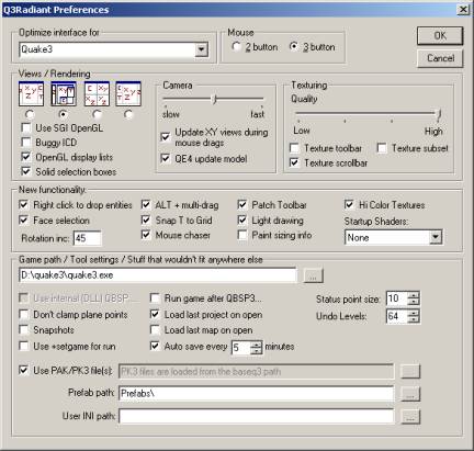
Optimize Interface for
Choosing Quake2 or Quake3 in this list will reset certain
preferences to the appropriate defaults for the selected game. Currently, the
default is Quake3.
Mouse
This lets you choose between two or three-button mouse
operation. The default setting is three-button operation. A three-button mouse
is HIGHLY recommended for Q3Radiant.
Views / Rendering
These preferences allow you to choose between one of four
general layouts for the various editing windows and set the way that rendering
is handled. If you are coming to Quake
III Arena editing from a Quake engine editing tool (or from a tool for
another game engine), you may want to select a layout set up that is familiar.
That being said, we also suggest you check out the “id” way of working.
Split Window view
 This
is the QeRadiant default view. The Camera, XY Map, Z-axis Scale, Texture, and
Console windows are constantly displayed. While the arrangement of the windows
cannot be changed, their size is adjustable by pulling the window border
splitters. The Entity and Group windows share a common pop-up window. This
arrangement is one that may work particularly well for mappers using smaller
monitors and slower computers.
This
is the QeRadiant default view. The Camera, XY Map, Z-axis Scale, Texture, and
Console windows are constantly displayed. While the arrangement of the windows
cannot be changed, their size is adjustable by pulling the window border
splitters. The Entity and Group windows share a common pop-up window. This
arrangement is one that may work particularly well for mappers using smaller
monitors and slower computers.
Floating Window view
 This
is the view used by id designers. The position, arrangement, and size of the
windows are all adjustable. The windows initially come up on top of one another
(a known bug), but once positioned, this view offers the greatest flexibility.
The Camera, XY Map, Z-axis Scale, and a shared Entity/Texture/Console/Group
window are all displayed simultaneously. Changing the size of one window does
not automatically affect the others (it can lay atop the others). Additional
map layout views can be cycled from menu commands or bound keys. This view only works well if you have a
20+-inch monitor.
This
is the view used by id designers. The position, arrangement, and size of the
windows are all adjustable. The windows initially come up on top of one another
(a known bug), but once positioned, this view offers the greatest flexibility.
The Camera, XY Map, Z-axis Scale, and a shared Entity/Texture/Console/Group
window are all displayed simultaneously. Changing the size of one window does
not automatically affect the others (it can lay atop the others). Additional
map layout views can be cycled from menu commands or bound keys. This view only works well if you have a
20+-inch monitor.
Make it Big! In floating windows mode (ONLY), you can double-click
on any window’s Title Bar to enlarge the contents of the window to fill the
screen. Double clicking on it again reduces it back to normal size.
Quad view
 The
display window is split into four equal-sized windows: Camera, XY Map, YZ Map,
and XZ Map. This is similar to other editors and offers four-way viewing. You
see the map components in three views simultaneously. The size of the windows
(relative to each other) can be adjusted, by pulling the splitters. The
combined Entity/Texture/Console/Group window is brought into view as a single,
floating window that lays over the others. The Z-axis window is not used in
this view. This is a popular editing configuration, but it has significant
performance issues. The editor is drawing all the 2D map components three times
(plus maintaining a camera view). Some mappers have notice significant performance
slow-downs when working with curves. Using the Quad view is only recommended
for mappers with more powerful computers.
The
display window is split into four equal-sized windows: Camera, XY Map, YZ Map,
and XZ Map. This is similar to other editors and offers four-way viewing. You
see the map components in three views simultaneously. The size of the windows
(relative to each other) can be adjusted, by pulling the splitters. The
combined Entity/Texture/Console/Group window is brought into view as a single,
floating window that lays over the others. The Z-axis window is not used in
this view. This is a popular editing configuration, but it has significant
performance issues. The editor is drawing all the 2D map components three times
(plus maintaining a camera view). Some mappers have notice significant performance
slow-downs when working with curves. Using the Quad view is only recommended
for mappers with more powerful computers.
Reverse Split Window view
 Essentially
the same as the Split Window view, except that the windows are all flopped left
to right.
Essentially
the same as the Split Window view, except that the windows are all flopped left
to right.
Use SGI OpenGL
This will cause Q3Radiant to load the SGI software OpenGL
drivers. If you do not have hardware OpenGL, these drivers will offer better
speed than the standard Microsoft drivers. You must download and install the
SGI OpenGL drivers for this option to work. Here’s a link to a direct download:
ftp://ftp.qeradiant.com/opengl/sgi/opengl2.exe
Buggy ICD
If you see garbled text in your 2D view windows, check this.
It changes the way Q3Radiant does font rendering which corrects an error in
some ICD's.
OpenGL Display Lists
This is only used for patches (bezier curves) in Quake III Arena editing. Turning this on
will speed up curve drawing by a large factor.
Solid Selection Boxes
Selecting curves, models, or large numbers of brushes causes
a noticeable slowdown the Nvidia series. This is an uncorrected driver issue.
Solid selection boxes are a workaround for that problem. Checking solid
selection boxes reduces the performance hit by turning the dashed line boxes
solid.
Camera
Camera
The slider allows you to set how fast the camera moves.
Update XY Views during Mouse Drags
When interacting with the camera (which you will do a lot),
turning this off will NOT update the camera icon location in the Map windows
automatically. This can help with speed but prevents you from seeing exactly
where the camera icon is positioned.
QE4 Update Model
Leave this on unless you’re running on a very slow system
with software OpenGL.
Texturing
Quality
This slider allows you to set the quality of the graphics
displayed in the editor. The higher the quality setting the better the textures
will look AND the more memory they consume. Setting the quality lower, reduces
the overall visual quality of the textures
(but ONLY in the editor, not in the final level), but can also drastically reduces memory consumption.
If you are having performance problems, this is one option to set back right
away.
Texture toolbar
This provides a texturing toolbar. This feature may or may
not work. According to Robert Duffy, it hasn’t been tested in about 100 builds
of the code. That means use it at your own risk. But here’s what it appears to
do:
It puts a texture toolbar at the bottom of the program
window. The toolbar has six data fields.
Five of them have up and down scroll arrow.
Shift H: This shifts the texture horizontally in pixel increments equal to
the current map grid. Values cannot be typed in.
(Shift) V: This shifts the texture vertically in pixel increments
equal to the current map grid. Values cannot be typed in.
Scale H: Multiplies the texture’s horizontal size by a multiple of the
current grid scale. Scaling of textures does not appear to function as it may
have been intended.
(Scale) V: Multiplies the texture’s horizontal size by a multiple
of the current grid scale. Scaling of textures does not appear to function as
it may have been intended.
Rotate: This
rotates the texture clockwise or counterclockwise (using the scroll arrows).
The rotation increment (or decrement) uses the degree value set in the field
(unnamed) to its immediate right.
(degrees): This
value is only used by the rotate
command on the toolbar and no others. It does not affect the information
entered on the preferences field. The value must be typed in.
Texture Subset
This provides a texture edit window within the texture
window. It is still buggy as of build 188. It puts a text field at the top of
the Texture window. Type in the first few letters of a texture name and the
window will only display the textures beginning with that letter or letters.
Texture Scrollbar
This adds a Windows scrollbar to the texture window. You can
use it (or the customary right mouse drag within the window) to scroll the
texture window.
New functionality
Right click to drop entities
This lets you to right click in a Map Window to get a Pop-up
menu that allows entity dropping among other things. Remember that a click is different than a press since a right press allows you to
move around the map as well (see Moving
Around under Map Building Basics).
Face Selection
If this is checked, the surface dialogue references and
pulls it contents from the selected face (ONLY if a face and not an entire
brush). If this not checked, the editor uses the current default texture
(selected in the texture window) as the source.
Rotation Inc
This is the default rotation increment used by the keyboard
shortcuts and the button bars for all types of texture, brush, and patch
rotation.
ALT + Multi-drag
If this option is checked, you must hold down the ALT key to
drag multiple brush edges. This lets you resize more than one brush at a time.
Snap T to Grid
This snaps the Texture tweak size to the grid size. The texture tweak size is the amount
textures are moved with the texture toolbar and the keyboard shortcuts.
Mouse chaser
Turning this on causes the view to chase the mouse if you
drag something off the edge.
Patch Toolbar
This enables the Quake3 specific toolbar that contains patch
(bezier curve) shortcuts.
Light drawing
This draws lights as shaded triangle things (octahedrons)
instead of standard square entities. When enabled, the light entities also show
their emitted light color.
Paint sizing info
This draws size information on the selected item(s). It also
draws in real time when dragging out a new brush or altering the size of an
existing one.
Hi Color Textures
This causes the editor to load 24 and 32 bit TGA and JPEG
textures. This should be checked for Quake3 editing.
Startup shaders
Allows you to specify which shaders are preloaded when the
editor starts. The default is None. Options are None, Custom, and All. Loading all of the shaders at editor load time
is VERY time consuming.
Game Path/ Tool Settings/ Stuff that wouldn’t fit anywhere else
Game
Set this to point at the proper game executable (Quake3.exe,
for example). This is not properly set up automatically, as of build 181 and
must be set manually.
Use Internal (DLL) QBSP
This is for Quake2 only and is grayed out for Quake 3
editing. The internal DLL is not provided with Q3Radiant. If you want to use
it, you will need to acquire it from an earlier release of QERadiant. To get
the .DLL for Quake 2 usage, you will need to download QERadiant
from this site:
http://www.qeradiant.com/files.cgi?dirin=qeradiant/latest/
Don’t clamp plane points
This turns off clamping of plane points. This allows for
very precise brush/vertex manipulation but can make it difficult to get things
properly aligned and can also cause the bsp process to take a LOT longer. In
general, this should be unchecked.
Design Tip: Be
warned, if at any point during design you change to a snap to grid setting, you
may see everything you’ve worked on twist and deform to lock into grid
coordinates. If you want to work to
work in very fine detail, use a 1-unit map grid. But even then, you’re asking for headaches you don’t need.
Autosave
Checking this forces the editor to automatically save the
map to the autosave name specified in project settings based on the selected
time increment. This feature has saved more than one mapper’s bacon.
Snapshots
This saves an incrementally named snapshot of the user’s map
based on the autosave time increment. The problem is it can quickly fill a hard
drive, as there is no space checking in force. Current recommendation is to
leave this feature turned off.
Run game after QBSP3
This will run the game pointed to by the game path with a
+set map “yourmap.bsp".
Warning. With
some video drivers, it is a bad idea to run Quake
2 or Quake III Arena and the Q3Radiant editor. The drivers just will not
sustain two demanding OpenGL applications simultaneously. This feature is best
left turned off.
Load last project on open
This causes the editor to load the last project file (.qe4)
when it is re-started. This is a good thing.
Undo Level
There are a maximum of 64 levels or layers of Undo. This
field lets you choose how many you want to use. Unless you are having serious
memory problems, this it’s good to leave it set at 64 layers.
Use +set game for run
This is broken as of build 181. Its intended purpose is to
allow mod's to run properly when the editor (using run game after QBSP3) starts
the game.
Load last map on open
This causes the editor to load the last map when it is
re-started.
Status point size
This sets the point size for the status bar font. A 10-point
font is the default.
Use PAK/PK3 files
Checking this will cause the editor to load the specific PAK
file for Quake2 or *.PK3 file(s) in the basepath for Quake3.
Prefab path
Allows the user to specify the path from which the editor
will to load prefabs (premade map components).
User .ini path
Allows you to specify an INI file that contains custom key
bindings. Most of the commands in Q3Radiant can be bound to specific key
combinations. The .ini file should
contain a section called 'commands' and a binding for each command you want to
rebind under that. You use the normal
character for most keys but there are special names for certain keys. You can
modify each binding with a ‘+ SHIFT’ or ‘+ CTRL’ or ‘+ ALT’. You can also
combine things like:
SurfaceInspector = F4 + SHIFT + ALT
And so on.
Here is an example keymap file (note that this is NOT the
default keymap):
[Commands]
NextView = TAB
BendMode = O
UpFloor = PAGEUP+shift
DownFloor = PAGEDOWN+shift
TexRotateClock = PAGEDOWN
TexRotateCounter = PAGEUP
CameraForward = E
CameraBack = S
CameraLeft = Q
CameraRight = T
CameraUp = F
CameraDown = D
CameraAngleUp = A
CameraAngleDown = G
CameraStrafeRight = R
CameraStrafeLeft = W
CenterView = 0
CenterOnCamera = U
GridDown = [
GridUp = ]
ViewConsole = F1
ToggleConsole = F1
ViewTextures = F2
ViewEntityInfo = F3
SurfaceInspector = F4
EntityList = F6
MapInfo = F7
ToggleGrid = F8
ToggleCamera = F10
DragEdges = B
DragVertices = V
CloneSelection = SPACE+shift
DeleteSelection = BACKSPACE
UnSelectSelection = SPACE
NextLeakSpot = L+ctrl+shift
PrevLeakSpot = K+ctrl+shift
MouseRotate = R+shift
FlipClip = ESCAPE
ZoomIn = Y
ZoomOut = H
ZZoomOut = DELETE
ZZoomIn = INSERT
TexDecriment = END
TexIncriment = HOME
TexScaleDown = DOWN+ctrl
TexScaleLeft = LEFT+ctrl
TexScaleRight = RIGHT+ctrl
TexScaleUp = UP+ctrl
ToggleClipper = X
CycleGroupSelection = C
ToggleSizePaint = P
Copy = C+ctrl
FileOpen = O+ctrl
FileSave = S+ctrl
Exit = X+ctrl
Undo = Z+ctrl
Patch TAB = L
MakeOverlayPatch = P
ToggleView = V+shift+ctrl
ToggleZ = Z+shift+ctrl
ConnectSelection = K
ShowDetail = F9
MakeDetail = M
SelectNudgeDown = DOWN+shift
SelectNudgeLeft =
LEFT+shift
SelectNudgeRight = RIGHT+shift
SelectNudgeUp =
UP+shift
Preferences = F11
The project file contains the paths for the various
Q3Radiant file-processing functions. Using the installer to set up the editor
should write these for you.
New Project
(Menu: FileèNew
Project)
This creates a new folder (which you must name) in your Quake III Arena directory.
This is really only needed if you’ve messed up your
project settings (without overwriting the original), and you want to reload the
defaults.
Load Project
(Menu: FileèNew
Project)
This opens up a browse directory pointed at the scripts
directory. It is looking for a text file with a .qe4 file extension.
Changing the Project File
(Menu: FileèProject
Settings…)
You can edit the project file by changing the pathnames to
various functions in field of the dialogue window that pops up. HOWEVER, before doing this, you should make
a backup copy of your Quake project file and give it a new name. Make your
changes to this new file. If you mess things up, you can always reload the
original. This is a good thing to do if you are making maps for a mod that uses
a separate set of definitions for entities or directories for textures and want
to easily change between types of projects.
Project Settings
Basepath: This traces a path, beginning in your root directory to
the baseq3 where the editor expects to find resources.
Mapspath: This traces a path, beginning in your root directory, to
the location where maps are saved and from which they are loaded. The default
is the maps directory.
Rshcmd: The means “remote shell command.” Use it only if you are
directing a remote processing device (not your editing computer) to compile
maps. The syntax for the field is: “rsh [processor name]”
Remotebasepath: If you are running your compile from your editing
computer, this should be the same as your basepath. If you are working off a remote compling device, this should
trace the full path to the to the baseq3 folder where the compiler will find
the resources it requires.
Entitypath: This traces a path to the definition file for your game
entities. This can either be a .c file which contains the game code, or a .def
file which contains more instructive information about the entities.
Texturepath: This traces a path, beginning in your root directory,
to the location from which textures are loaded. The default is the textures
directory.
Menu commands
These commands are your map compile commands. You can
CHANGE these commands or ADD your own. Each new command must start with “bsp_”
The following is the compile command string for “bsp_Fullvis” taken off one of
our project files.
! q3map $ && ! q3map -vis -threads 8 $ &&
! q3map -light -threads 8 $
Command parameters:
! The exclamation mark is replaced by the
contents of the rshcmd field. It is the path to the processor.
$ The
dollar sign is replaced by the Mapspath.
&& The
double ampersand is the command terminator (end of command)
q3map This is the
process command. Without a switch after it, it performs the .bsp compile phase.
-vis This is
a switch to select the vis compile phase.
-light This is a
switch to select the lighting compile phase.
-threads This is a switch to break the compile
up into a number of different processor threads. The number of processors
follows the switch parameter.
Other parameters
-onlyents Process only the entities in the map.
-fast A quicker process. However, it treats the map as if
it were all one vis area.
-extra As in -light -extra. This is a second lighting pass that
more finely subdivides the map into areas of light and shadow.
-nowater Compiled without liquids in the map.
Used in the first compile phase only.
-nocurves Compiles without curves in the map. Used in the first
compile phase only.
Misc settings
Use brush primitives
in MAP files.
Once this is set for a map, the program converts the texture
mapping to this format. Once chosen, there is no going back to the old format.
Brush primitives are described in detail under the Working with Textures
section.
There are six configurable windows in Q3Radiant.
The Camera Window (CAM)
The Camera window initially shows a gray field. This is where the 3D in-progress view of
your map appears. You can SHIFT + click
mouse button 1 to select objects in this window. If the images in this window appear overly dark, you can adjust
the gamma value. Open the Misc menu and select Gamma. Enter a value between 0
and 1 for the light value. Close the program. Reopen the program. Check the
darkness. Repeat this until you have a value you like.
Entity/Texture/Console/Group Window
Depending on the Windows layout view that you’ve chosen,
one or more of the following sub-windows share this window. They are selectable
by the tab at the bottom of the window, or by shortcut keys.
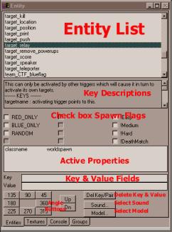
Entity Window
(Shortcut: N)
The Entity window is one of four windows that share the
same window space: Console, Entity and Texture and Group. The entity window is
used to create and modify the properties of game entities. The uppermost box in
this window contains the entity names. Use the scroll bar to find the one you
want or for speed, type in the first letter of the class of entity you desire
(“w” for weapon, “I” for item and so on). Refer to the Working with Entities
section for more details on this.
Texture Window
(Shortcut: T)
The Texture window displays textures that have been loaded
from the texture directories for easy use. The texture subset tool (set in
preferences) allows you to quickly jump to a texture if you know the first few
letters of its name. The scrollbar tool adds normal Windows functionality to
the window. The most common method of navigating the window is to right-mouse
click and drag through the window contents. SHIFT + right-mouse click and drag
speeds up the rate of movement through the window’s contents. A thin green
outline around a texture indicates a non-shadered texture in use in the map. A
thin white outline indicates a shadered texture. A bold red outline indicates a
selected texture.
Console Window
(Shortcut: O)
The console tracks the editor’s processes, like loading,
saving, and compiling. When you compile
(selecting an option from the bsp menu), the contents of the console are dumped
into the junk.txt file in your Temp file folder on your root drive. In the
Split Window view layout, the Console window is always in view.
Groups Window
(Shortcut: none)
This window will deal with the future grouping functions
that will soon be a part of the editor. At this time, it is only a
non-functioning window.
Z-axis Scale Window
This window is used by three of the four views to show the
Z-axis position (height) of the Point of View and any selected map components.
Map Window(s)
The Grid
Think of the Map window as a piece of graph paper, neatly
divided into squares. However, unlike graph paper, you can change the size of
the grid to fit your needs of the moment. You can change grid size from the
Grid menu, but it’s faster to learn the key shortcuts listed below.
Setting Grid Size
Grid size Key
1 unit grid (1)
2 unit grid (2)
4 unit grid (3)
8 unit grid (4)
16 unit grid (5)
32 unit grid (6)
64 unit grid (7)
Grid Down Decreases
the size of the grid. [ key
Grid Up Increases
the size of the grid. ] key
Grid and Window Layouts
There are four distinct ways of laying out the work windows
for Q3Radiant.
Design Notes:
Try not to build architecture with a grid smaller than 8
units.
Use a smaller grid if you need to build small details.
Use a large grid (32 or 64) for roughing in a level.
Use a large grid for moving large chunks of architecture
around.
Snap to Grid
When this is checked, the edges and vertices of brushes and
patches will “snap” to grid coordinates. Unless you are attempting some very
fussy maneuvering of a map component, Snap to Grid makes life much easier. In
fact, if you are building objects out of curve patches, it is crucial that you
be able to line up patch control points with the vertices of surrounding solid
geometry brushes.
Colors
Q3Radiant allows you to select the colors of your grids and
tools. Because the manual refers to the colors of some features, you may wish
to wait until you are more comfortable using the editor before changing too
many things. You can always revert to
the Q3Radiant defaults, should you choose change too much.
To change Map window and Texture window colors, select the
“Misc” menu and choose colors. The pop-up lists a number of options.
Themes
Brings up three
options:
QE4 Original: The settings for id’s original Quake 2 editor
Q3Radiant Original: The default setting.
Black & Green: a black background with a green grid major.
Each of the following options opens the Windows color
selector.
Grid Background…
The background color for the map window.
Texture Background…
The background color behind the textures in the texture
window. This is probably best left a neutral color.
Grid Major…
These bolder grid lines mark 64 unit increments in the map
window. These never change.
Grid Minor…
The finer grid lines in the map window.
Grid Text…
The color of the scale numbers along the left and top of the
map window.
Grid Blocks…
These lines mark the 1024 x 1024 unit grids on the map.
Default Brush…
This is the color of unselected brushes in the map.
Selected Brush…
The color of selected brushes in the map.
Active View Name…
This is the text that says “XY Top” or “YZ Side” or “XZ
Front” in the map view window(s).
Quake III Arena
divides map components into two classes: World Geometry and Entities. World Geometry represents the brushes (the
Q3A term for the blocks of geometry used to build the physical game world) and
patches (anything built with calculated curves). Entities are a broad category that not only includes simplistic
editor representations of game play objects like weapons and ammo, but also
includes diverse things like player start spots, and lights. Typically, they
are displayed as brightly colored cubes (for those entities not constructed of
brushes). The following are the general
category of entity types. The actual entities and the rules and tips for their
use are listed in the Appendices.
Brush entities. The “brush”
is the basic building block of Quake engine games (including Quake, Quake 2, Quake III Arena, and a host of games using the engine
licenses). In its most basic form, it’s
a block, a solid rectangular volume defined by the coordinates of its corner
vertices. A single brush or a linked
grouping of brushes can be turned into a brush entity. Brush entities include the movers (see
below), triggers, and func_statics.
Movers. Most moving objects or “Movers” are built from brushes.
These include doors, lifts or “plats”, rotating objects, buttons, pendulums and
trains (objects following pre-defined paths), and bobbers (platforms that are
constantly in motion, up and down or side to side).
Triggers. Triggers are brush entities that cause an event to occur
when a player’s bounding box moves inside the volume of the trigger. Triggers
can be targeted on many other entities, including most movers and targets. Some triggers also have more specialized
functions. There are triggers that
cause injury, activate other entities, and push or teleport the players.
Targets. Targets are the entities that are activated to cause
events to happen in Q3A, or to
redirect activations, insert time delays, mark locations for team play, or act
as destination points for teleportation or pushing.
Lights. These are point lights, disembodied (read as no visible source)
sources of illumination. They ca n be targeted at info_nulls to create
spotlights. They can be turned into colored lights. Usually, they are used to
create unfocused fill light in a large area or placed near glowing surface
textures to create an effect.
Info. This category includes non-team player spawn spots, targets
for lights, and camera locators for intermission shots.
Items. With the exception of ammo and weapons, these are things in
the map that the players grab to use during play. Included are armor, power ups like the quad, and one-use items
like the personal teleporter.
Ammo. Locations for ammo boxes. Each weapon type in Q3A has its own unique ammo entity.
Weapons. Each of the
weapons that can be picked up has an entity that can be placed.
Miscellaneous. This is another catchall category. It includes
things like the misc_model which links into the models directory when placed,
func_timers which are automated repeating triggers, shooters which fire one of
three different weapon fire types, camera and portal surfaces, and path
corners.
Assets
are the textures, sounds, and models that are used to flesh out the appearance
and ambience of a game map. The editor
is designed to use the assets stored in the pak0.pk3 file in your quake3
directory. Using Q3Radiant, the mapmaker can work with the assets in the Quake III Arena pak0.pk3 file or create
new ones.
What are Textures?
The art
appearing on the walls of maps are generally referred to as “textures.” Textures are created and stored as true
color targa (.tga) or jpeg (.jpg) graphic files. The textures do not use a
pre-defined color palette (as was the case with both Quake and Quake 2).
Shader scripts can further combine textures and/or modify them in numerous
ways. This document will briefly touch on shaders. For an in-depth treatment of
shaders, refer to the accompanying Shader Manual.
What are Sounds?
Quake III Arena world sounds are played by target_speaker entities in the
maps. They are stored as 22 khz, 16-bit, mono format .wav files.
What are Models?
The
statues and lights in Q3A are models, just like the player characters. They are placed with the misc_model entity.
If you
are familiar with the required tools, creating new assets for use in Quake III
Arena is not particularly difficult. As a rule, you should create new
directories for each map with names different from the names used by id. If you
are making a map that will be called “H4x0r_D00M”, every directory containing
new assets for that map should be titled H4x0r_D00M. This is to try and avoid
asset directories overwriting each other as the editor and the game load in
assets.
Creating Textures
Any
combination of graphic programs and plug-ins that can output a 24 bit MS
windows compatible Targa (.tga) or JPEG (.jpg) graphic file. If you plan to
make textures that will have an alpha channel component (see glossary for
definition), you must have a program that can create 32-bit art with that
fourth channel.
Adobe PhotoShop has the ability to
easily create alpha channels. Paint Shop Pro from JASC (v5.0+) can also make an
alpha channel by creating a mask and naming it “alpha”.
Generally speaking, regardless of
the program used, we found it best to do most of the art manipulation of the
alpha channel in a separate layer or file and then paste it into the alpha
channel before saving.
Setting up Files
The editor and the game program look for assets to be
located along the paths set up in your project file. Start by creating a
directory for you new textures by creating file folders to make a directory
path as follows: quake3\baseq3\textures\[mymapname]
The installation of Q3Radiant will create a text document
called “shaderlist.txt” in the following path:
Quake3\baseq3\scripts\shaderlist.txt
Q3Radiant will use the contents of
this script to grab your new textures for inclusion in the game. The contents
of shaderlist.txt document will contain a listing of all the shader documents
that were used by id Software to create Quake
III Arena.
Since you will obviously want to
create your own shaders, you need to put them in separate folders and create a
new shader script for them.
If you plan to work on several maps
at once and want to distinguish between textures used in each map, simply add
additional map names here. For map and mod makers, we STRONGLY recommend that
any new shader scripts created use the name of the map or mod in the shader
file name. We know we can’t avoid every incident of files overwriting each
other, but we certainly can advise you how to try.
Now, create another text file within the scripts directory
and call it:
[mymapname].shader
This file will contain the shader scripts you write to
modify a particular texture.
Rules
Follow these rules when creating
textures for the Quake III Arena
engine:
·
Save your textures into your new [map name]
directories.
·
Don’t use the same names that id used for textures. It
will cause problems.
·
For best quality, save textures without an alpha
channel as 24 bit TARGA files. Using JPEG files can save memory space, but at
the risk of losing detail and depth in the texture. JPEG files cannot be used
for textures requiring an alpha channel.
·
Textures containing an alpha channel must be saved as
32 bit TARGA files.
·
If a new texture requires no further manipulation, it
does not need a shader script.
·
Size textures in powers of 2. Example: 8x8, 16x16,
32x32, 64x64 pixels and so on.
·
Textures don’t need to be square. A 32x256-pixel
texture is perfectly acceptable.
Guidelines
The following are some things the id designers learned about
textures.
·
Create textures in “suites” built around one or two
large textures with a number of much smaller supporting detail or accent
textures.
·
Very large textures are possible, but some video cards
compress textures larger than 256x256 pixels.
·
Textures are grouped alphabetically by name in the
texture display window, so you may want to give suites of textures similar
names.
·
Use the shader function qe3_editorimage to conserve
memory when making multiple versions of a single texture (as in the case of a
glowing texture with several light values).
·
Unless you are creating special effects or textures designed
to draw the player’s eye to a specific spot, muted, middle value colors work
best with the game engine.
·
Extremely busy (a lot of fussy detail) textures can
break up or form visually unpleasant patterns when seen at distances.
Creating Sounds
Tools needed: Any sound editing program that can create and save
out sound files as 22 khz, 16-bit, mono format .wav files.
Set up: The editor and the game program
look for assets to be located along the paths set up in your project file.
Start by creating a directory for you new textures by creating file folders to
make a directory path as follows: quake3\baseq3\sounds\world\[map name]
Place your completed .wav files in
the [map name] folder. You can access (and play) this file from within the
editor (see instructions for Target_Speaker).
Creating Models
Map
models need to be converted from their native file format into Quake III Arena’s native md3 file
format. The modeling program, Milkshape 3D supports the file format needed to
create map models for Quake III Arena (a link for this program is in the
On-line Resources appendix). The compiling process merges the models into the
bsp file. If you want other mappers to be able to use your models, you will
need to include the md3 and supporting texture files within your pk3.
When you go to distribute your creation to the gaming world,
you need to put your newly created map, textures, bot area files, and shader
documents into an archive format called a “pk3” file. You do not need to include the shaderlist.txt file, since only
the Q3Radiant editor uses that. Start by creating folders/directories in your
root drive (C: for most of us). The game assumes that these folders are placed
in the baseq3 directory, so you need to write your path names accordingly. You
will need to keep the paths to the various assets the same as they are for the
rest of the assets in the game. So your paths should be something like this:
Textures:
textures/[mymapnamefolder]
New Models:
models/mapobjects/[mymodelnamefolder]
Map, bsp & aas:
maps/mymapname.bsp , mymapname.aas
Shader scripts:
scripts/mymapname.shader
Server scripts:
scripts/mymapname.arena
Move or copy all your new game assets in their folders.
We used an archiving program call Winzip to make the pk3
file. Get Winzip from http://www.winzip.com/winzip/winzip.htm
NOTE: Do not
include or redistribute any game assets that are not your own (at least without
permission). This specifically refers to id-copyrighted material that came with
the original game or subsequent id released patches.
Make a zip archive called “map-mymapname.zip”
If you plan on distributing other resources separately, we
strongly recommend the following naming conventions:
md3-xxx.pk3 User Model with original associated skin
files and sound files
bot-xxx.pk3 User bot files. May contain
additional model or skin and texture files
skin-xxx.pk3 User skin with associated skin and
texture files
map-xxx.pk3 User created map(s) and supporting files
(arena, texture, sound, music)
tex-xxx.pk3 User texture and shader files
snd-xxx.pk3 Sounds only
mus-xxx.pk3 Music only
pfb-xxx.pk3 Map prefabs
(special thanks to Rogue13 of http://www.polycount.com for this naming
convention)
When you go to add a resource to the archive, click on
options to “Recurse Folders” and “Save Extra Folder Info”
Zip all the required assets into a zip archive file (Quake III Arena DOES support compressed
pk3 files).
Put it where the Quake
III Arena community can find it.
My .pk3 File is Huge! No One is downloading it!
Large pak files are daunting as downloads. And as
specified by the Quake III Arena End
User License Agreement, that is the only way those new game assets may be
distributed. Be kind and remember that not everyone has access to DSL, ADSL,
ISDN, Satellite, Cable Modem or other high speed internet connections. Before
packing up your resources, you may want to look into some dieting tricks to
make it smaller.
·
First, resave all your new non-alpha channel textures
in JPG format. That will give you some significant art size savings.
·
Streamline your map’s art package. Id designers had to
go on a rip ‘n strip rampage through their levels to cut down on unique texture
usage. Do you really need all that additional art? Can you substitute more of
the original Q3A art, or get more
duty out of some of your new work?
·
Recompile your area files with the optomize switch.
That will reduce their size. That's why it's in there as a command. This is
also one of the biggest savings that you can make.
·
Turn up the level of compression when archiving into
the pk3 file.
·
Compress again when zipping up the files.
·
Take a SERIOUS look at any new sound resources you've
created. Sounds, especially long sounds can be HUGE! Can short sounds be
cleverly used to replace longer sounds in your map? The id designers did a
bunch of that for Q3A. Very short
sounds, played off sync against each other were made to sound like longer, more
expensive sound files.
Once you have the editor installed and the preferences set,
open the map and let’s get started.
There are a number of ways to move your point of view around
in the map and camera windows. Some are easy to master. Others are a bit
trickier. Find one that works for you and master it.
Moving in All Directions
All movement directions are given relative to directions
in the XY map. When other map views are shown, movement is still calculated in
terms of the XY view. Key press movement occurs in discrete increments.
Forward (in facing direction) (Up Arrow Key) or (Keypad 8)
Turn left (Left
Arrow Key) or (Keypad 4)
Turn right (Right Arrow Key) or (Keypad 6)
Backward (Down Arrow Key) or (Keypad 2)
Move up (D)
Move down (C)
Look up (A)
Look down (Z)
Level View (END)
Flying … through the Map (and other 3D commands)
Some mappers prefer using mouse-fly to move around their
map. Mousefly works by clicking and pressing with the Mouse button 2 (Right
mouse button) on the Camera window. This takes a lot of practice to master.
Clicking farther away from the window center increases the speed of movement.
Forward (in facing direction) (Right Mouse click above window center)
Turn left (Right
Mouse click left of window center)
Turn right (Right Mouse click right of window center)
Backward (Right Mouse click below window center)
Move up (D)
Move down (C)
Look up (A)
Look down (Z)
Level View (END)
Zoom with a View
The zoom keys increase or decrease the visual scale of the
map, letting you move in close to work with small details or move away to see
the entire map at once. Currently, there are 24 steps of zoom, from most
distant to closest. If Quad view is used (XY, YZ, and XZ views simultaneously),
all three windows may zoomed at different scales. The Z-axis scale window is
also zoomed separately
Zoom in
(DELETE)
Zoom out
(INSERT)
Z-axis Zoom in
(CTRL + DELETE)
Z-axis Zoom out
(CTRL + INSERT)
Jump to Location
(CTRL + Middle Mouse Button)
Click on a 2D map or the Z-axis window and your point of
view immediately moves to that location. In the 2D map windows, neither the
facing, nor the “height” of the point of view changes.
Moving the Maps Around
A right-mouse-button click and drag on a 2D Map window
will cause the map to be dragged, allowing you to easily reposition what is
being viewed.
This is a simple, step-by-step guide to making your first
room. Before attempting it, you may want to familiarize yourself with some of
the Brush selecting and handling tools. A Quake
III Arena aficionado who goes by the handle “The Dog!” posted this simple
on a Quake III Arena on-line message
board. It appears here with his permission.
It will walk you through creating a new map file, making your first
“brush,” adding a start spot and a light and then compiling the map.
The Dog!’s Ten Quick-n-Dirty steps to a SIMPLE room:
1) Create new map:
a) click file,
new map
2) Create a small hollow room (make a box and hollow it out):
a) Make a box. In the XY Top window, click/hold your left
mouse button at coordinates 256,-256 (upper left) - then drag your mouse to the
-256,256 (lower right) [you should see a red square appear in grid].
b) Make the box taller. In the Z
Window (this is also called the
height bar): This brush appears as a red box. Click/hold your left mouse button
above the upper edge of the box and drag that bar up to about 256. [you have
just raised the height of the box]
c)
Make it hollow. On your Toolbar below the Menu bar, locate the 'Make
Hollow' Button (should be a red box with a dotted box inside of it
)located under the M in Misc). Press
that button. This breaks the box up into six pieces: four walls, a ceiling and
a floor. [you should now see a hollow
room in the texture view window]
3) Press Escape to
deselect the box (you are finished with room/box for now).
4) Add a player
starting point:
A) Bring up the Easy Entity Menu. With
your pointer over the room in the XY Top
window, right mouse click INSIDE the newly created room box to open up the easy
entity menu.
B) Place a Start Spot. Select info, then
select info_player_deathmatch. [you
should see a small pink box appear - this is where you will start in this map
anytime its loaded]
C) Is it in there? Make sure that your new
starting point is 'really inside' the room that you have created.
1) Click the xyz
button on your toolbar so that you can toggle through each 'view' of
that coordinate (XY top, XZ front, or YZ side).
2) Watch the
red box (info_player_deathmatch) as
you toggle through each view to make sure the red box is inside room
3) If there
is a view it is not located inside - simply stop and drag it inside the box.
(You can learn how to put it in optimal places later), until it is totally
inside the room.
5) Press Escape to
deselect the info_player_deathmatch item.
The box now turns into a solid pink, box outline.
6) Now add some
textures:
A) Load up Textures. Click on the texture menu and drag down to
select the gothic_wall texture directory.
B) Open Texture window. Press “T” to open the texture window. It
should be full of wall textures.
C) That wall will do just fine. Then
decide what wall surface you want to apply the texture to. Hold the left-CTRL
and the left-SHIFT key down and then left click on a wall. The wall will turn
red.
D) Pick a Texture, any Texture. in the
'texture view' window, left mouse click on any wall texture. A red border will now surround this texture.
And presto, the wall becomes that texture too.
E) Repeat this
step for all the walls that you want to apply textures to.
7) Save your
map.
The editor doesn’t like to work with “unnamed” map files.
From the menu, select File è Save. Name the map “test1”. Always use lower case
for your map names.
8) Add a light.
A) Bring up the Easy
Entity Menu Again. With your pointer over the room in the XY Top window, right-mouse-click INSIDE
the newly created room box to open up the easy entity menu.
B) Place a Light. Select info, and then
select light. [You should see a
small red box appear (smaller than the player start).
C) Move it into place. Do the same
procedure you did for the player start spot, making sure that this light is
inside the room.
D) Deselect the light. It will become a
green box.
9) Compile it.
In the BSP menu, select “bsp_fastvis”. Wait patiently for
the program to finish three phases of compile: bsp, vis, light.
10) Start ‘er up.
Start your Quake III Arena game. When the menu appears, hit the tilda key (~). On most American
keyboards, this is in the upper left corner of the keyboard, below ESC.
A)
Enter the Devmap.
In the console, type “\devmap test1” and then ENTER.
B)
Play it for all it’s
worth. The map should start and you will be standing in the center of your
first room.
Now go make something more complicated on your own!
The most basic interaction with the editor is selecting
and deselecting the map components. Everything else builds off from these
commands.
Escape (ESC)
This is the all-purpose deselect key. Use it to back out of
operations you don’t want to complete or to stop working on a map component or
group of components.
Select single component
(SHIFT + mouse button 1 while mouse pointer is over desired
unselected component)
In the XY Window (or XZ or YZ), this selects a single map
component that is “closest” to the top of all components beneath the pointer.
The following is an exception: If an entity is directly beneath the pointer, it
will be chosen in preference to a non-entity, even if the non-entity is
“between” it and the pointer.
Select single face on brush
(SHIFT + CTRL + mouse button 1 while mouse pointer is over
desired unselected brush face in the Camera Window).
This selects a single face on one brush, not the brush
itself.
Select multiple faces on one or more brushes
(SHIFT + CTRL + ALT + mouse button 1 while mouse pointer is
over desired unselected brush face in the Camera Window).
Use this to select several brush faces on one or more
brushes.
Cycle through stacked components
(SHIFT+ALT+mouse1 while pointer is over map view)
Beginning with the component that has the greatest Z value,
the user can cycle through vertically stacked components that are directly
beneath the mouse pointer.
Deselect single component
(SHIFT+mouse1 while mouse pointer is over desired selected
component)
In the XY Window (or XZ or YZ), SHIFT clicking on a selected
component deselects it. The following is an exception: If a selected entity is
directly beneath the pointer, it will be chosen and deselected in preference to
a non-entity, even if the non-entity is “between” it and the pointer.
Deselect all selected components
(Menu: SelectionèDeselect)
(Shortcut: ESC)
All selected components are deselected.
 There
are four commands for selecting large groups of components. These involve
creating a brush that encloses or touches numerous other components. In most
cases, the brush used to create the grouping is deleted by the operation. These
operations can be selected by menu commands or by buttons on the toolbar. The
toolbar buttons are in the third grouping (as counted from the left). The
command buttons on the toolbar are given as they relate to the Selection
sub-grouping on the toolbar.
There
are four commands for selecting large groups of components. These involve
creating a brush that encloses or touches numerous other components. In most
cases, the brush used to create the grouping is deleted by the operation. These
operations can be selected by menu commands or by buttons on the toolbar. The
toolbar buttons are in the third grouping (as counted from the left). The
command buttons on the toolbar are given as they relate to the Selection
sub-grouping on the toolbar.
Design Note:
These grouping commands are particularly useful when you want to region off a
small area of the map.
Select Complete Tall
 (Menu: SelectionèSelect Complete Tall)
All brushes from the top to the bottom of the map that are
totally enclosed within the XY dimensions of the grouping brush will be
selected. The grouping brush is discarded.
WARNING: Undo
will restore selected components but will delete the selection brush.
Select Touching
 (Menu:
SelectionèSelect
Touching)
(Menu:
SelectionèSelect
Touching)
All brushes that are in contact with the grouping brush will
be selected. The grouping brush is NOT discarded.
Design Tip: Need
to work an area around a particular brush? Use this tool to select the brush
and then use the selected brushes to create a regioned area.
Select Partial Tall
 (Menu:
SelectionèSelect
Partial Tall)
(Menu:
SelectionèSelect
Partial Tall)
All brushes from the top to the bottom of the map that are
touched by the XY dimensions of the grouping brush will be selected. The
grouping brush is discarded.
Select Inside
 (Menu:
SelectionèSelect
Inside)
(Menu:
SelectionèSelect
Inside)
All brushes from the top to the bottom of the map that are
totally enclosed by the XY and Z dimensions of the grouping brush will be
selected. The grouping brush is discarded.
Save Selected
(Menu: File)
The selected brushes are saved as a map file. Not a true
prefab, but a way to duplicate pieces of a map for later insertion.
Copy brush
(Menu: Edit)
(CTRL+C)
This function copies all hi-lighted brushes, patches, and
entities onto clipboard. Contents of clipboard may be pasted into the current
open map file or into another open map file.
Paste brush
(Menu: Edit)
(CTRL+V)
The map information previously copied into the clipboard is
pasted at the same XYZ coordinates as the original. UNDO will delete the paste.
Clone
(Menu: SelectionèClone)
(Shortcut: SPACE)
Selected map components are immediately duplicated. The
clone appears +1x and -1y units (current map grid) away from the original (down
and to the right). The clone remains hi-lighted until deselected.
Save Selection as Prefab
(Menu: EditèSave
Selection as Prefab)
(Shortcut: none)
The user is
prompted to save the selected map components as a prefab file (*.pfb) in the
directory set by Preferences.
Load Prefab
(Menu: EditèLoad
Prefab)
(Shortcut: none)
Opens a file selection window into the directory set in
Preferences. Select from that directory or browse for another. The selected
prefab is pasted into the map at the same XYZ coordinates as the original.
Delete
(Menu: SelectionèDelete)
(Shortcut: BACKSPACE)
All selected map components are removed from the map.
Undo
(Menu: EditèUndo)
(Shortcut: none)
Undo will undo
recent command actions affecting brush geometry, curve patches, and in-map
comands that affect entities (move, rotate, delete, etc.). Undo has no effect
on texture operations.
The number of
levels or layers of Undo can be set in Preferences. The maximum number is 64.
Unless your computer memory is extremely low, there is no real reason to use
less than all 64 levels of Undo.
Regions are an important tool to learn and use early on.
Whether you isolate off a single brush, or half a map, you’ll wonder how you
ever got along without this tool in other editing programs. The selections on
the Region Menu allow the mapper to isolate, and work on, a subset of the map.
There are innumerable benefits to working in a “regioned” area of the map.
However, the following are the most important:
·
It allows you to work with a few map components at a
time, without the distraction of the rest of the map pieces.
·
When you want to perform CSG operations, regioning lets
you isolate the pieces from the rest of the map, reducing risk of making
unwanted cuts or splits.
·
Map regions can be compiled without having to compile
the rest of the map. This can be an incredible timesaver. Instead of spending
hours to compile an entire map just to check for leaks in new construction, or
check the appearance of a room, or test a lighting effect, minutes can be spent
processing just the room itself.
There are several ways to select a region, by a group
selection, by XY map window dimensions (or the corresponding view in YZ and
XZ), or by a few selected map components.
The commands for selecting regioned areas are found under
the Region Menu heading.
Region Menu
Off
(Menu: RegionèOff)
This returns you back to the full map. Brushes that were
selected while in the regioned mode remain selected until ESC is pressed to unselect
them.
Set XY
(Menu: RegionèSet
XY)
Any map components that are inside, or that are touched by
the bounds of the XY Map window are converted into a region. The size or shape of the window does not
matter. Nor does the degree of Zoom matter.
This is an excellent way to select are larger subset of your map, such
as a complex room or group of rooms. Any brushes selected before regioning the
map remain selected.
Set Tall Brush
(Menu: RegionèSet
Tall Brush)
This functions in a similar manner to the group selection
command, Select Partial Tall. Any map components contained within the XY
bounds, or touching the XY bounds of the brush will be regioned off. The selecting brush itself is discarded.
Set Brush
(Menu: RegionèSet
Brush)
This functions in a similar manner to the group selection
command, Select Touching. Any map components contained within the XYZ bounds of
the brush, or touching the XYZ bounds of the brush will be regioned off. The
selecting brush itself is discarded.
Set Selected Brushes
(Menu: RegionèSet
Selected Brushes)
If you need to work with just a few brushes, this is the
option to choose. Hi-light the brushes to be worked upon then select this
option. Only those brushes are moved to the region. The selected brushes are
unselected when the region is created.
Compiling Notes:
Sometimes, when compiling a regioned area, md3 map object models near the edge
of the region can cause a “false leak” situation to occur. This can usually be
corrected by adjusting the region size to include more of the map near the md3
map object model.
The geometry brushes are the basic building block of the
Quake III Arena engine. These are the tools to make them work for you.
Escape (ESC)
This is the all-purpose deselect key. Use it to back out of
operations you don’t want to complete or to stop working on a brush or group of
brushes.
Create New Brush
(Click mouse button 1)
(Shortcut: none)
While mouse1 clicking over the main map window (or any open
map window) drag the mouse pointer across the grid. A brush will be created
that has the height of the current map grid size. If you have the “snap to
grid” function set in your preferences, the brush will start and stop on
gridlines. The texture will be either the default texture (if none has been
selected) or the most recently used texture. For all these functions, you will
first need to select a brush in either the Map or Camera windows.
Move Geometry Brush
(Click mouse button 1)
The Undo command will return the brush to its original size
(if the brush is still selected). If the brush has been deselected, the resized
version will remain and another brush will be created at full size.
In the Map Window. In the
map window, select the brush. Click on the selected brush. With the mouse 1
button depressed move the brush around the map to the position you desire.
In the Z (height) Window. In the map window, select the brush.
Next, click on the selected brush in the Z window. With the mouse 1 button
depressed move the brush around the map to the position you desire.
In the Camera Window.
Select a brush in the camera window (see select single component
above). Mouse button 1 click on the
brush and drag it in the desired direction. You may need to adjust your camera
view to make dragging easier.
Stretching the Brush
(mouse1)
Think of this as stretching the brush. The Undo command will
return the brush to its original size (if the brush is still selected). If the
brush has been deselected, the resized version will remain and another brush
will be created at full size.
In the Map Window. In the map window, click next to the selected
brush on the side you want to pull. With the mouse 1 button depressed pull in a
direction away from the nearest edge. The brush will grow larger in that
direction.
In the Z (height) Window. Use this to make the brush taller. In the Map or Camera window,
select the brush. Next, click above or
below the selected brush in the Z window. With the mouse 1 button depressed
pull away from the select brush. The brush will grow in that direction.
In the Camera Window.
Select a brush in the camera window (see select single component
above). Mouse1 click near the edge of
the selected brush. With the mouse 1 button depressed pull in a direction away
from the nearest edge. The brush will grow larger in that direction. You may
need to adjust your camera view to make dragging easier.
Shrinking the Brush
(mouse1)
Think of this as crunching the brush smaller.
In the Map Window: In the map window, select the brush. Click next to the selected brush on the side
you want to pull. With the mouse 1 button depressed pull in a direction toward
the nearest edge. The brush will shrink in that direction.
In the Z (height) Window: Use this to make the brush shorter. In
the Map or Camera window, select the brush.
Next, click above or below the selected brush in the Z window. With the
mouse button 1 depressed, push towards the select brush. The brush will shrink
in that direction.
In the Camera Window: Select a brush in the camera window (see select
single component above). Mouse1
click near the edge of the selected brush. With the mouse 1 button depressed
push in a direction towards the nearest edge. The brush will grow larger in
that direction. You may need to adjust your camera view to make dragging
easier.
Flip Brush
(Menu: Selection èFlip)
There are three separate actions here. They flip a brush along either X, Y, or
Z-axes. A menu command and toolbar button controls each. The six flip and
rotate toolbar commands are the second grouping (from the left) on the
toolbar. The rotate command for the
same axis is always next to the flip command. Flipping will not change the
facing on non-model entities.
Flip X (Menu: Selection) (Toolbar:
Leftmost button)
Flips
brush along x-axis.
Flip Y (Menu: Selection) (Toolbar: left
of center button)
Flips
brush along y-axis.
Flip Z (Menu: Selection) (Toolbar: second button from the right)
Flips
brush along z-axis.
Rotate Brush
(Menu: Selection èRotate)
There are three separate actions here. They rotate a brush in 90 degree increments
around a brush’s X, Y, or Z axes. Both a menu command and toolbar button
controls each action. The six flip and rotate toolbar commands are the second
grouping (from the left) on the toolbar. The flip command for the same axis is
always next to the rotate command for the same axis. The rotation will not
change the facing on non-model entities.
Rotate X
(Menu: Selection èRotateèRotate
X)
Rotates
brush around the x-axis.
Rotate Y
(Menu: SelectionèRotateèRotate
Y)
Rotates
brush around the y-axis.
Rotate Z
(Menu: SelectionèRotateèRotate
Y)
Rotates
brush around the Z-axis.
Arbitrary Rotation
The Rotate commands accessed from the toolbar all rotate
affected map components 90 degrees; no more, no less. Arbitrary Rotation allows
the user to set angles individually for the X, Y, and/or Z-axes. Enter a number
value for each axis you want to rotate. Value can be positive or negative.
After the values are entered, select OK. This rotates the object and closes the
pop-up window. If you don’t like the rotation, you can use Undo, so long as the
brush is still selected, and the brush will return to its un-manipulated
facing.
Free Rotate in Map Window
(Shortcut: R)
Press the “R” key. The selected map component(s) turns
lavender. The purple square at the center is the center of the selection and
the axis around which it will rotate. Left Mouse clicking on or near the
selected component (in the map or camera window) and dragging will cause it to
rotate. If the user does a SHIFT + middle mouse button click on the 2D map window, the axis square will
relocate to the coordinates of the click. Deselecting and reselecting the
component returns the axis to its original center.
Drag
There are two “drag” functions that involve control points
or “handles” on the brush.
Drag Edges
(Menu: SelectionèDrag Edges)
(Shortcut: CTRL + E)
This highlights the edges of a geometry brush, marking
those edges with a blue “handle” box at the center of each side. Press again
and the feature will toggle off. Pull on a handle to resize part of a brush. If
Snap-to-Grid is active (Menu: Grid),
the handle will snap to the nearest grid coordinate as it is pulled. Undo
functions with this effect.
Drag Vertices
(Menu: SelectionèDrag Vertices)
(Shortcut: CTRL + V)
This highlights the corner vertices of a geometry brush,
marking those corners with a green “handle” box where the sides of each brush
face connect. Press again and the feature will toggle off. Pull on a handle to
resize part of a brush. If Snap-to-Grid
is active (Menu: Grid), the handle will usually snap to the nearest grid
coordinate as it is pulled. Undo does NOT function with this effect.
Design Note:
Drag Vertices is a balky tool at best. It works well if the user is
manipulating a triangular brush face, raising or lowering corners of the
triangle. Work with care, it is quite easy to pull a brush out of useable (or
recoverable) shape.
Scale
(Menu: SelectionèScale)
With Scale you can enlarge or reduce a brush, patch, or
group of brushes and patches. You choose the axes to scale (X, Y, or Z) and the
factor of the scale. The scaling factor can be different for each axis.
Selecting this option brings up a tool window. The size of the brush or group
of brushes is multiplied by the numbers in the boxes adjacent to the X, Y, or Z
axes. Leave the value as 1 and no change occurs. If the value is a decimal less
than one, the size of that axis shrinks. If the value is greater than 1, it
grows. Hit OK to activate the scaling function with you chosen values. Undo
functions with this effect.
CSG Operations
CSG stands for “Computed Solid Geometry”. The two functions here, CSG Subtract and Make
Hollow, calculate the removing of sections from that geometry and
breaking solid brushes (not curve patches) into smaller pieces. Although they are convenient to use for some
operations, they often do things that the user may not care for. These “side
effects” can include breaking brushes into inconvenient parts, cutting up
adjacent brushes, and creating hard to find and remove micro brushes.
Subtract
 (Menu:
Selection è
CSGè Subtract)
(Menu:
Selection è
CSGè Subtract)
When you select this, the
selected brush or brushes subtract its volume from all the geometry that
contacts it. The cutting brush is not removed. Undo does not fix this action.
Design Note: Region off together the brushes that will be cut and
the brushes which will be used for cutting. This keeps other brushes in the map
from being affected by the action. It’s also a good idea to save just before
doing the action, so the user can “back up” to an earlier version.
Hollow
(Menu: Selection è CSGè
Hollow)
 When
the user selects this, the sides of the highlighted brush are turned into
separate brushes. The thickness of these brushes is equal to the grid size.
Undo functions with this action.
When
the user selects this, the sides of the highlighted brush are turned into
separate brushes. The thickness of these brushes is equal to the grid size.
Undo functions with this action.
Design Note: This works best with rectangular brushes. The edges of the created brushes overlap
each other.
Merge
(Menu: Selection è CSGè
Merge)
 When
the user selects this, the highlighted brushes are turned into a single, convex
brush. If the result of the merge would not create a convex brush, the
following message appears in the editor console: “ Cannot add a set of brushes
with a concave hull.”
When
the user selects this, the highlighted brushes are turned into a single, convex
brush. If the result of the merge would not create a convex brush, the
following message appears in the editor console: “ Cannot add a set of brushes
with a concave hull.”
Examples:
Example “A” shows two brushes can be
merged together. Example “B” shows
two brushes that cannot merge.
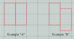
Clipper
(Menu: SelectionèClipper)
(X toggles the clipper tool on or off)
 If
you think of this tool as being near the same as the miter box that a carpenter
uses to cut wood or moldings, then you are not far from the truth.
If
you think of this tool as being near the same as the miter box that a carpenter
uses to cut wood or moldings, then you are not far from the truth.
Placing Clip Points
Clip points are placed in the map views by two methods:
(Mouse button 1 after Clipper has been toggled on)
(CTRL + Mouse button 2 at any time)
The figure below shows a square brush that has been
“clipped” from the lower left (point 1) to the upper right (point 2). The
editor creates a line between the first point and the second point. The piece
to be kept when the brush is cut is always created in a clockwise direction
from the line (assuming that the first point is the center of the “clock”)
In a two-point clip (shown here), the cut occurs
perpendicular (at a 90 degree angle) from the plane of the map view. Adding a
third point, and adjusting its position in a different map view can change the
angle of the cutting plane. This will take practice to master.
Toggle Clipper
(Menu: Selectionè
ClipperèToggle
Clipper)
(X)
This toggles the Clipper function
on and off. After completing a cut, the tool remains active and must be toggled
off before another brush is selected.
Clip Selection
(Menu: Selectionè
ClipperèClip
Selection)
(SHIFT)
If the “clip
selection” action is completed the red portion of the brush will be discarded
and only the yellow will remain. The brush is unselected. Undo currently
returns the original brush and keeps the clipped off piece.
Split Selection
(Menu:
Selectionè
ClipperèSplit
Selection)
(SHIFT +
CTRL)
If the “split
selection” action is completed the red and yellow portions of the brush will
remain, split into two triangular brushes. The brush is unselected.
Flip Clip Orientation
(Menu: SelectionèClipperèFlip
Clip Orientation)
The yellow and red hi-lights toggle so what was red
is now yellow and what was yellow is now red.
Make Detail
(Menu: SelectionèMake Detail)
(Shortcut: CTRL + M)
In Quake 2, this
was a surface flag. In Quake III Arena,
it is used on the brush itself. Detail makes a brush non-structural. This means
that it cannot be used to seal the hull of the map world. Don’t use it for
wall, floors, or ceilings. If it is used as a hull, the map will “leak” when
compiled. But it can be used on things that jut out away from the walls (as
long as there is a structural brush behind it).
Detail has two beneficial effects:
1. Detail brushes are less likely to cause additional cuts
to occur in non-detail brushes that they touch ... thus reducing triangle
counts. This can help reduce frame rate.
2. When the compiler does Vis, it breaks the world up into
many small volumes. Any break in the surface of the box that forms a room
creates additional volumes that must be. Detail brushes don't create these
breaks. Therefore, using them speeds up compiling.
Make Structural
(Menu: SelectionèMake Structural)
(Shortcut: none)
Structural is the Default State for brushes. Textures that
are not manipulated by shader scripts to be transparent or non-solid) do not
change this. Essentially, this is a change-it-back
command for Make Detail. It removes the detail flag from the brush. This
surface WILL block Vis when the map is compiled (so long as there isn’t shader
content that says otherwise).
Func_Group
(Entity WindowèFunc_GroupèEnter)
Technically, this is a b_model (brush model) entity.
However, it’s a great way to manage and handle related groups of map components
for ease of selection. To use, select
the brushes and patches you want to group and then open the Entity window
(press “N”). Click on the entity list sub-window and type in “F” to move to the
top of the “funcs”. Double-click on Func_Group and all the brushes and patches
selected are bound together into a group. Select one and you select them all.
Thumb through Components
(Shortcut: TAB)
When you have a Func_Group b_model entity selected, press
the TAB key to “thumb” through the component pieces, hi-lighting them individually,
one at a time. This allows you to work on part of a multi-piece group without
having to work on all pieces
Find Brush
(Menu: MiscèFind
Brush)
Find brush allows you to locate a brush in the map by its
identifying number. As the map is
built, the editor assigns identification numbers to each map component. For
brushes (and patches) these include an Entity number and a brush number. For
any brush that is not part of a brush model (b_model), the entity number is
zero (0). Each b_model will have it’s own number.
When the compiler outputs error messages in the console
and junk.text file, an identification number will call out brushes with
problems. Be prepared for them. Even when you do things right, you will get
error messages.
Selecting Find brush pops up a dialogue window with two
fields. The first field is the entity number. For most brushes, this will be
zero. The second number is the brush’s individual number. Selecting “OK,” jumps the 2D map window(s)
to the selected component and hi-lights it.
Brush scripts…
(Menu: EditèBrush
scripts…)
(Shortcut: none)
The command allows you to perform multiple step operations
that manipulate a single brush. Currently, only two of the list scripts
function.
BuildSpiral This walks you through the steps of building a spiral
staircase. Select a brush, then click on the map to locate the spiral origin.
Click again to bring up a dialogue window that prompts you to enter the number
of steps, the angle of rotation, and the height of each step.
BuildStep This
clones the selected brush and moves it +X 16 units and +Z 8 units.
The Brush menu lets the mapmaker convert a selected brush
into a brush of a different shape. Most of the commands change the number of
sides that the brush possesses. It will also change the brush to a single
color. There are individual commands for three through nine sides. The brush
will be given the number of sides indicated by the command (Plus top and
bottom). The “top” facing is always relative to the view in which it is
created. The sides are always at right angles to the view facing.
Poly-Sided Brushes
3 sided (Menu: Brushè3 sided) (Shortcut:
CTRL + 3)
4 sided (Menu: Brushè4 sided) (Shortcut:
CTRL + 4)
5 sided (Menu: Brushè5 sided) (Shortcut:
CTRL + 5)
6 sided (Menu: Brushè6 sided) (Shortcut:
CTRL + 6)
7 sided (Menu: Brushè7 sided) (Shortcut:
CTRL + 7)
8 sided (Menu: Brushè8 sided) (Shortcut:
CTRL + 8)
9 sided (Menu: Brushè9 sided) (Shortcut:
CTRL + 9)
Arbitrary sided…
(Menu: BrushèArbitrary
sided…)
This command opens a dialogue window. You can enter a number
of sides in the field from 3 to 64. Select OK to execute the command.
Primitives
(Menu: BrushèPrimitives)
Primitives are pre-made shapes other than squares or the
polygonal multisided boxes made by the “number” sided brush commands.
Cone…
(Menu: BrushèPrimitivesèCone…)
This opens a pop-up
dialogue window that lets you enter an arbitrary number of sides. The height of
the cone is equal to the Z height of the brush. The cone is always made with its
axis along the Z-axis. At first, the radius of the base of the cone appears to
be unrelated, or at least unevenly related to the XY dimensions of the brush
from which it is transformed. However, if you make a four sided brush, the
point to point “diameter” of the resulting pyramid is equal to the longest XY
dimension of the brush. Starting the same size brush as you used for the
four-side cone, an eight-sided cone fits neatly within the volume of the
four-sided cone, four of its sides congruent with the side planes of the
four-sided cone. Do the same for a 16 sided cone, and the same again for both a
32 sided cone. However, the number of sides seems to max out at 56.
Sphere…
(Menu: BrushèPrimitivesèSphere…)
This opens a pop-up dialogue window that lets you enter an
arbitrary number of sides. The maximum number of sides, which the editor seems
willing to handle is 32.The diameter of the sphere, is roughly equal to the
length of the longest XY side of the brush from which it is transformed.
Attempts to create spheres with more faces than 32 may result in the brush
disappearing and becoming infinitely tall. Use Undo to back up from this or hit
backspace to discard the brush.
Torus…
Non functioniong command.
No donuts for you!
Moving the Brush
These keys move the brush around the map in discrete map
grid increments.
Move Selection Down
(Shortcut: Keypad MINUS)
Each press moves the selected map component down
along the Z-axis by one grid position (at current grid setting). Not affected by
current 2D-map view.
Move Selection Up
(Shortcut: Keypad PLUS)
Each press moves the selected map component up
along the Z-axis by one grid position (at current grid setting). Not affected
by current 2D-map view.
Nudging the Brush
These keys move the brush around the map in discrete map
grid increments. The movement is in terms of the selected window, not in terms
of XYZ coordinates.
Nudge Down
(Shortcut: ALT + DOWN ARROW)
Each press moves the selected map component “down”
the map view by one grid position (at the current grid setting). The movement
is relative to the selected map view, not XYZ coordinates.
Nudge Up
(Shortcut: ALT + UP ARROW)
Each press moves the selected map component “up”
the map view by one grid position (at the current grid setting). The movement
is relative to the selected map view, not XYZ coordinates.
Nudge Left
(Shortcut: ALT + LEFT ARROW)
Each press moves the selected map component “left”
the map view by one grid position (at the current grid setting). The movement
is relative to the selected map view, not XYZ coordinates.
Nudge Right
(Shortcut: ALT + RIGHT ARROW)
Each press moves the selected map component “right”
the map view by one grid position (at the current grid setting). The movement
is relative to the selected map view, not XYZ coordinates.
Snap Selection To Grid
(Shortcut: CTRL + G)
If you are using the map grid to keep brushes in
alignment, this is a great tool. Rotated brushes and brushes that have had
their vertices tweaked can have vertices that no longer lie on map grid
intersections. This snaps the vertices to align with the grid. Be warned that snapping to large grids may
be hazardous to the health of your brush (Snap and it’s gone! But that’s what
UNDO is for).
Developed from a Quake
3 World online posting by Astrocreep
Compiling a map is a necessary evil. It takes time, it ties
up your processor, and in the early phases of map construction, comes up with
construction errors as often as not. Nothing you can do about that … except the
time thing. It is possible, through
more careful construction (or perhaps reconstruction) to significantly reduce
both map and bot compile times, and reduce map and .bsp file sizes (the latter
being important for downloads). The following is based on reports written by
Astrocreep that documents his extensive work to streamline the compile on one
of the id sample maps.
Brush Construction
It cannot be overstressed. If you want shorter compile times
and small file sizes, efficient brush construction is "critical" in
building your map. There is one rule that stands above all:
DO NOT OVERLAP BRUSHES AT ANYTIME.
No matter what you have to do to build your map, do not
overlap brushes. Overlapping means that
all or parts of two or more brushes share the same physical space. If brushes
overlap, you can expect to add time to your compiling, and add size to your
.map, .bsp and, .aas file sizes.
Efficient map construction means that all brushes butt up
against each other, but never intersect.
Brush Counts
The sample map to be reworked on had 1,100 brushes in it.
Without changing the layout or appearance of the map, Astrocreep was able to
remove 110, or 10% of the total brush count.
Learn how to do more with a single brush than with multiple
brushes. Evaluate your map after you complete initial construction phases on
all or part of it. Pick a part of the
map, look at the layout and ask yourself if you could do that with fewer
brushes. In all likelihood, nine times out of 10, the answer will be yes.
If you make a structure out of three brushes (or whatever)
and have the same floor height and ceiling height (in some cases heights can be
different), look at it in the "top view". Can you draw a line from
each vertex and not cross out side of those three brushes? If you can, then
that grouping of three can become one brush instead of three.
Example: here’s
how the engine might look at this.
Using 3 square brushes, you have 18 faces (with a texture
mapped on each side) to be calculated. This doesn’t take into consideration the
number of in-game triangle faces that those brushes may generate. Even if
two-thirds of those faces are not being drawn, they are still being calculated
by both the compile process and the bot navigation compile process.
As compared to:
Using one brush (filling the same area), you have only 6
faces to be calculated. Here, you are compiling only a third of the total
geometry. It should go faster.
Efficient map construction means using fewer brushes to
build the world.
Caulking
It is possible to even further reduce the number of brush
faces being calculated by applying a special non-drawing, but “solid” texture
called “caulk” (common/caulk) to surfaces that cannot be seen in the game. When
seen in the editor, this texture is a bright garish pink. In the game, it does
not draw at all. Apply caulk to any brush face that either doesn’t form the
“shell” of the world or can’t be seen by a player during play. Doing this may
not improve your map’s frame rate, but since your are telling the compiler that
as many as five of the six faces on a square brush don’t have to be calculated,
it should have some significant effects on compile times. As long as you do not
have any brushes that “share” the same space, caulking brushes should help reduce
compile times. However, if you use caulk on a brush that “shares” the space of
another, your compile time and all file sizes will actually increase.
Astrocreep compiled the test level nearly 200 times, many of
those times were when he moved just a single brush, just to see what would
change. Caulking seems to help the -light
phase of compiling the most.
Efficient map construction means caulking all unseen brush faces.
Miscellaneous Tips
Lights: You can
further improve compile times by careful use of lights. Entity lights,
especially LOTS of entity lights can reduce compile time. If you need to reduce
compiling time even more look to this.
Clip brushes:
Clip brushes that have more than two sides not touching another brush appear to
increase compile times.
Hint brushes: Use
these only if you need to resolve a vis problem. Using them can significantly
add to compile times.
Escape (ESC)
This is the all-purpose deselect key. Use it to back out
of operations you don’t want to complete or to stop working on a patch or group
of patches.
The next set of commands comes from the Curve Menu. Some are
duplicated on the Patch Tool Bar.
Cylinder
(Menu: CurveèCylinder)
This creates the simplest cylinder. Cylinders are always
drawn with their open ends facing up and down. It does not matter which map
view is open when the cylinder is created.
More Cylinders:
(Menu: CurveèMore
Cylinders)
Dense Cylinder
This is a cylinder with a set of
extra rows. It allows a 180-degree bend into a half donut (half torus).
Very Dense Cylinder
This is a cylinder with two extra
sets of rows. This allows a bend into a full donut (torus).
Square Cylinder
This is a cylinder whose columns
have been adjusted so that a square, with flat sides, is formed.
(Menu: CurveèEndcap)
This is a half cylinder.
Bevel
(Menu: CurveèBevel)
This is a quarter cylinder
More End caps, Bevels:
(Menu: CurveèMore
End caps, Bevels)
Square Endcap
This is an endcap without the
backside removed.
Square Bevel
This is a bevel with squared off
back faces
Cone
(Menu: CurveèCone)
A cone is a cylinder with control points drawn together and
welded at one end to form a point.
Sphere
(Not implemented)
Design Note: A
curve patch sphere can be constructed from a cone. Start with a cubic brush.
Convert into a cone. Go into edit vertexes mode and grab the control point at
the peak of the cone. Pull it downward
to half the height of the cone. Clone the resulting piece and flip it upside
down.
Simple Patch Mesh…
(Menu: CurveèSimple
Patch Mesh…)
The patch mesh is the basic building block use to create
all curves. All the curve primitives
are deformations of this item. For this to work, you must first create a brush
of the dimension desired for the patch. Selecting this opens a Patch dialogue
window. This lets you select the vertical (rows) and horizontal (columns)
complexity of the patch. The more complexity means being able to perform more
deformations on the patch. It also means adding a greater number of triangles
that must be rendered.
Insert
(Menu: CurveèInsert)
Adding control points increases the complexity of a mesh.
This action does not increase the physical size of a mesh. Additions are
usually done before manipulating the patch mesh.
Insert (2) Columns
This adds two columns of control
points to the left edge of a patch.
Add (2) Columns
This adds two columns of control
points to the right edge of a patch.
Insert (2) Rows
This adds two rows of control
points to the lower edge of a patch.
Add (2) Rows
This adds two rows of control
points to the upper edge of a patch.
Delete
(Menu: CurveèDelete)
Deleting control points reduces the complexity of a patch
mesh. Be warned that the features created by the removed points are also
removed. It does not make the mesh a less complex version of the former design.
Deletions also change the dimensions of the mesh, removing the area created by
the deleted control points. A mesh cannot be reduced smaller than a 3 column by
3 row complexity.
First (2) Columns
This removes two columns of
control points from the left edge of a patch.
Last (2) Columns
This removes two columns of
control points from the right edge of a patch.
First (2) Rows
This removes two rows of control
points from the lower edge of a patch.
Last (2) Rows
This removes two rows of control
points from the upper edge of a patch.
Matrix
(Menu: CurveèMatrix)
This has nothing to do with Neo and Trinity. It’s the patch
mesh taken as a whole.
Invert
(Menu: CurveèMatrixèInvert)
(Shortcut: CTRL + I)
This command inverts the
normals of the patch mesh. The normals control the direction of facing for the
texture skin and the clipping surfaces.
Re-disperse
(Menu: CurveèMatrixèRe-disperse)
This is used on a selected patch. When rows or columns are
inserted or added to a patch, the dimensions of the patch are not changed. The
distances between the new additions and the old points are not the same. This
command averages out the distance between the points. It does not change the
size of the patch. WARNING! Only
apply this BEFORE adjusting the patch. Otherwise, you may lose your work on it.
With some patches, selecting this command will destroy the patch itself.
Cols
(Menu: CurveèMatrixèRe-disperseèCols)
(Shortcut: SHIFT + CTRL + E)
The distance between columns is averaged and evened
out.
Rows
(Menu: CurveèMatrixèRe-disperseèRows)
(Shortcut: CTRL + E)
The distance between rows is averaged and evened
out.
Transpose
(Menu: CurveèTranspose)
(Shortcut: SHIFT + CTRL + M)
(Function undetermined)
Cap
(Menu: CurveèCap)
This command adds “cap” patches to the ends of the patch.
The original brush and the caps are linked together as a func_group entity. A
Patch Tool Bar button duplicates this command. The type of cap depends on the
selected patch:
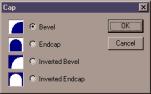
Cylinder The ends of the cylinder are sealed with
circular patches.
Square Cylinder The ends of the cylinder are sealed
with square patches.
Cone Both ends are capped (open and point).
You will want to discard the cap on the point end.
Bevel If you select
to cap a bevel, a dialogue window pops up.
A
normal bevel cap covers the space between the curve and the center.
Inverted Bevel An inverted bevel covers the space
between the curve and the outer corner.
Endcap If you select to cap
an endcap, the same dialogue window pops up.
Patch Mesh The bevel/endcap window will
pop up. Results will vary depending on the manipulations done to the mesh.
Square Bevel Capped in the same manner as a
cylinder
Square End
Cap Capped in the same manner as
a cylinder
Cycle Cap Texture
(Shortcut: CTRL + SHIFT + N)
Press this repeatedly until the texture on the cap patch
looks correct.
Overlay
(Menu: CurveèOverlay)
Overlay turns the grid of control points on for the selected
patches and leaves them on until the Clear command is selected. By having the
control points on a curve patch be visible, it is easier for the designer to
align the vertices of adjacent solid geometry brushes.
Set
(Menu: CurveèOverlayèSet)
(Shortcut: Y)
This is the command to turn on
the control points in a selected patch.
Clear
(Menu: CurveèOverlayèClear)
(Shortcut: ALT + Y)
This is the command to turn off
all control points in all patches.
(Menu: CurveèThicken)
(Shortcut: CTRL + T)
If you think about
it conceptually, Thicken transforms a curve patch into a three-dimensional
object. It does this by duplicating the selected curve and moving it a distance
away from the copied curve, and, if the “seams” checkbox is checked, it will
cover the space between the original and the copy with patches. The distance
between original and copy is selected in a pop-up dialogue window. The
direction is determined by the facing of the curve’s normals (the textured
side). The duplicated curve appears on the opposite side of the textured face.
The resulting object depends on the nature of the curve primitive being
thickened. The following are some
examples:
Cylinder A
pipe is created. Checking “seams” caps the ends.
Bevel A matching bevel is created.
Checking “seams” creates a bent square tube.
Endcap A matching endcap is created.
Checking “seams” creates an arch.*
Patch
Mesh A mesh that echoes the
shape of the selected patch is created, but with XY dimensions smaller or
larger by the measure of the thickness (smaller if the normals are on the
concave side; larger if on the convex side).
·
Thickening an Endcap is not the best way to create this
shape. Bending a square cylinder will produce better results.
The patch tool
par is turned on in the Preferences.
Each of these buttons enables or disables a curve editing feature, or
initiates a process on a selected curve patch.
Don’t Select Curved Brushes
This button
toggles the ability to select or not select curve patches in the map. If turned
on (depressed), the user will not be able to individually select curve
patches. Group selections will still
include any curve patches within their boundaries.
Show Patch Bounding Box
This button
toggles the display of the bounding box that defines the limits of the patch.
On (button depressed) shows the bounding box.
Show Patches as Wireframe
This button
toggles the display of patches between a fully textured mesh (off) and a
wireframe-only mode (on). The wireframe mode makes it easier to see the
deformations of the mesh and allows the user to see some control points that
may be hidden by the texture when it is mapped on the mesh. It can also be a
performance-enhancer for the editor (by setting the view to wireframe until you
need to see the brush textured).
Design Tip: When manipulating the
control points on a patch mesh, using wire frame allows you to best see both
the control points and the deformations.
Patch Bend Mode
If a curve patch
is selected, this button initiates a multi-step bending procedure. There are tutorials available on several
sites that address the fine points of bending a patch, whether it is a cylinder
or a simple flat mesh. The ESC key will exit the procedure at any point. The
following are just the steps:
·
Select the patch (and only the patch).
·
Press the Patch Bend Mode button. This brings up an
instruction window that says:
“Use TAB to cycle
through available bend axis.
Press ENTER when the
desired one is highlighted”
This highlights
(turns pink) a row or column of patch control points. One of these control
points will likely be the axis for your bend. Pressing ENTER locks in your
choice and advances to the next step.
·
A second instruction window message appears:
“Use TAB to cycle
through available rotation axis.
This will LOCK
around that point. You may also
use Shift + Middle
Click to select an arbitrary
point. Press ENTER
when the desired one is
highlighted.”
This highlights
the specific control point around which the patch will bend. Pressing ENTER
locks in your choice and advances to the next step. You can also choose the control point by SHIFT + middle mouse
button clicking on the map window. The
click need not be within the bounds of the patch.
·
A third instruction window message appears:
“Use TAB to choose
which side to bend. Press
ENTER when the
desired one is highlighted.”
This highlights
the side or end of the patch (relative to the bend point) around which the patch will bend. Pressing
ENTER locks in your choice and advances to the next step.
·
A fourth instruction window message appears:
“Use the MOUSE to
bend the patch. It uses the
same ui rules as
Free Rotation. Press ENTER to
accept the bend,
press ESC to abandon it and exit
Bend mode.”
Clicking and
holding the Left mouse button on the map window and dragging it around will
cause the patch to bend. Pressing ENTER or ESC at this point will accept any
changes that you have made.
Redisperse Patch Points
This is used on a
selected patch. When rows or columns are inserted or added to a patch, the
dimensions of the whole patch are not automatically adjusted. The distances
between the new additions and the old points are not the same. This command
averages out the distance between the points.
WARNING: Only apply this BEFORE making
adjustments to the patch, otherwise you may lose your work on it. With some patches, the patch itself will be
destroyed.
CAP (put caps on the current
patch)
This is used on a
selected patch.
Design Notes:
Endcaps: Don’t cap endcaps with this tool. Make a pair of opposing bevel
caps that match the arch of the endcap
Messed Up Texturing: If an inverted
bevel endcap covers something other than an arc of a perfect circle, it is
likely that the texture won’t appear right when you apply the CAP function to
the texture. Press SHIFT + CTRL + P a few times until it looks right.
Weld Equal Patch Points (welds
equal patch points during moves)
(Patch Control
Bar only) This feature, when selected (button pressed in) causes control points
to weld together if they are moved to the same coordinates. Undo will undo the
move and the weld.
Drill Down (selects drill down
rows and columns)
When this is
toggled on (depressed), clicking on a control point in a 2D Map view selects
all the control points in the row or column beneath it.
Moving Selected Curve Patch
These keys move the curve patch around the map in discrete
map grid increments.
Move Selection Down
(Shortcut: Keypad MINUS)
Each press moves the selected map component down
along the Z-axis by one grid position (at current grid setting). Not affected
by current 2D-map view.
Move Selection Up
(Shortcut: Keypad PLUS)
Each press moves the selected map component up
along the Z-axis by one grid position (at current grid setting). Not affected
by current 2D-map view.
Nudging the Curve Patch
These keys move the curve patch around the map in discrete
map grid increments. The movement is in terms of the selected window, not in
terms of XYZ coordinates.
Nudge Down
(Shortcut: ALT + DOWN ARROW)
Each press moves the selected map component “down”
the map view by one grid position (at the current grid setting). The movement
is relative to the selected map view, not XYZ coordinates.
Nudge Up
(Shortcut: ALT + UP ARROW)
Each press moves the selected map component “up”
the map view by one grid position (at the current grid setting). The movement
is relative to the selected map view, not XYZ coordinates.
Nudge Left
(Shortcut: ALT + LEFT ARROW)
Each press moves the selected map component “left”
the map view by one grid position (at the current grid setting). The movement
is relative to the selected map view, not XYZ coordinates.
Nudge Right
(Shortcut: ALT + RIGHT ARROW)
Each press moves the selected map component “right”
the map view by one grid position (at the current grid setting). The movement
is relative to the selected map view, not XYZ coordinates.
Snap Selection To Grid
(Shortcut: CTRL + G)
If you are using the map grid to keep curve patches in
alignment, this is a great tool. Rotated curve patches and curve patches that
have had their vertices tweaked can have vertices that no longer lie on map
grid intersections. This snaps the vertices to align with the grid. Be warned that snapping to large grids may
be hazardous to the health of your curve patch (Snap and it’s gone! But that’s
what UNDO is for).
There are three skill and knowledge components to working
with textures as they regard Quake III
Arena. They are Texture creation, Texture Manipulation, and Texture
Application. Only the third, Texture Application, is absolutely necessary for making
maps. You need not master all three.
With the release of version 192, the Q3Radiant editor takes
a new direction in the way textures are mapped to the surfaces of brushes. The
texturing format will roughly be the same as the way textures are handled on
curve patches. While there are no changes to the user interface within the
editor, you should see a change in the way textures behave on brushes during
transformation operations like move and rotate. Because textures are mapped to the S and T coordinates of a brush
(as they are with curve patches), locked textures will now maintain their
positions on brushes when they are moved or located. Even complex rotations
should now be possible without the textures going askew.
Checking the Brush Primitives checkbox turns on this feature. (Menu:
Project Settings…èUse brush
primitives in map files). Once you change a map to Brush Primitives, you
cannot go back to the earlier method of texture mapping with that map. The
prudent mapper makes backups before making major changes to projects.
This is covered earlier in the manual.
Technically, each texture already has a default shader that
passes it through the pipeline to appear much as it does in the graphic program
that made it. A shader is a short
script, separate from the texture file, that the game engine uses to make
further adjustments to the texture's appearance or function. The shader is to Q3A what the surface properties flags
were to Q2, only ever so much more
powerful. If you plan on creating your own textures, you should get to know and
understand how shaders work. The Q3A Shader Manual contains the information you
need.
Shaders and Multi-Pass Texture Effects
(Drawn from an
original essay by Small Pile of Gibs)
Shaders give the mapper control over special graphics
effects that require multiple redrawing passes before they are finally
displayed on the game screen. Every shader that changes the visual component of
a texture uses these “Multitexture” effects.
Multitexture is ON by default in Quake
III Arena. It is turned off with the cvar, “set r_ext_multitexture 0
(entered in the console or bound to a key) – see the Debugging section in this
document for more details.
To understand how multitexture works, you need to
understand how the Quake III Arena
graphic engine renders a scene. All the faces you see in Quake III Arena are made up of triangles – you can see this by
using the cvar command “r_showtris 1.” Initially, each triangle adds one to the
"tris" number in r_speeds (the numbers that are used to estimate
whether a scene is too complex). With every frame that Q3A “paints”, it draws triangles onto the scene in layers, starting
at the back of the scene and drawing every triangle visible until it reaches
the front. It takes time to draw each triangle. If a triangle is painted with a
texture that is “see through” in some way (either transluscent, transparent, or
containing cut-outs), any triangles seen through that triangle must be redrawn
one additional time for each stage in the the shader. If a single transparent
triangle takes up the whole screen, for example, a glass window – The whole
area of the screen has to be redrawn. Each triangle of glass takes an entire
screen worth of “overdraw” and each extra stage on the glass adds another
screenful, which is why glass can be such a big framerate hit.
The simplest form of multitexture is a Lightmap. In most
cases, the Q3A engine first draws the lightmap (precalculated light and shadow
information). Then, on top of that, it adds in the information from the texture
art specified for that triangle using a special effect (blendfunc filter) –
which blends the lightmap with the texture to make areas of the texture look
light or dark. Using the cvar command “r_vertexlight 1” (Vertex Lighting instead of Lightmaps) stops
Q3 from drawing the lightmap triangles (which is why many gamers use vertex
lighting to gain additional playing speed).
Every extra stage in a shader is an extra triangle drawn
over and blended with the first triangle in a special way. Like the lightmap
example above, each additional stage requires an extra triangle to be drawn for
each frame. On certain 3D accelerator cards (like the TNT - TwiN Texture), the
multitexture effect cancels out the real cost of the first pass of blending.
The blending for the first additional stage is done before the triangle is
drawn. However, if the shader takes 3 stages (like all the shiny metal effects)
it costs an extra triangle for every triangle it is used on. Every extra
triangle used adds a triangle to the r_speeds triangle count. Because there are
cards that don’t automatically handle this first blending pass, the map maker
needs to occasionally check his r_speeds with the multitexture turned off.
These tools manipulate textures within the editor. They do
not create textures or shader scripts.
Escape (ESC)
This is the all-purpose deselect key. Use it to back out of
operations you don’t want to complete or to stop working on a brush face, a
brush, a patch, or a group of brushes or patches.
View Textures
(Shortcut: T)
This is only used in the four-view and floating windows
modes (as set in Preferences). It brings up the Texture selection window (also
accessible from a folder tab). If the Entity window is open, you may need to
click on a map view window first for the “T” command shortcut to work.
Show in Use
(Menu: TexturesèShow
in Use)
(Shortcut: U)
This command affects the content of the Textures window. It
filters the contents so that only those textures currently in use in the map
are displayed in the window.
Show All
(Menu: TexturesèShow
All)
(Shortcut: CTRL + A)
This command affects the content of the Textures window. It
“un”-filters the contents so that all the texture directories previously loaded
during the mapping session are re-displayed.
Surface Inspector
(Menu: TexturesèSurface
Inspector)
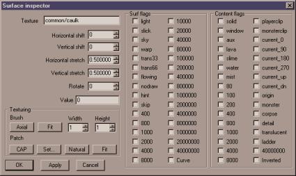 (Shortcut:
S)
(Shortcut:
S)
This brings up a pop-up dialogue box. This is one of the
more complicated interfaces used during map development and may take some
getting used to.
Texture
This is the path/name (beginning in Textures directory)
for the texture. You can copy from this field or paste into it. If you know the
pathname of a texture, you can enter it here. It will load without having to
first load the entire directory that contains it.
The next five commands work on both patches and brushes.
However, the results of applying a Horizontal Shift to a brush and to a patch
may be substantially different. When working with patches, the numbers in the
fields do not change … although the texture on the map component may be
changing.
Design Note:
When a curve patch butts flush up against a piece of solid geometry, as if it
were an extension of that geometry, it may be difficult to align the textures
exactly. In fact is often extremely
difficult to align a texture on a patch with the texture on an adjacent
geometry brush. It works best when the dimensions of the patch are an exact multiple
of the dimensions of the texture being used. Otherwise, you may want to
consider designing your architecture in such a way that it is logical for a new
texture to begin at that point. Use your judgement.
Horizontal Shift
This allows you to change the Horizontal texture offset
(position of texture on a surface). You can type an offset value into field or
use the scroll buttons on the right to shift the texture. If “Snap T to Grid”
is set in Preferences, the scroll increments will move a number of pixels equal
to the grid size.
Vertical Shift
This allows you to change the Vertical texture offset
(position of texture on a surface). You can type an offset value into field or
use the scroll buttons on the right to shift the texture. If “Snap T to Grid”
is set in Preferences, the scroll increments will move a number of pixels equal
to the grid size.
Horizontal Stretch
This allows you to change the dimensions of textures as
they are mapped into the world. You can type a size value into field or use the
scroll buttons on the right to enlarge or reduce the texture. The default value
is 0.5. This gives a presentation in the game world of two pixels for each game
unit. A Horizontal Stretch value of 1.0 would double the amount of area covered
by a single repeat of the texture. Of course, doing that also reduces the
apparent resolution of the texture by half (can you say blurry?)! Making the
stretch value a negative number horizontally flops the texture’s normals (i.e.;
flops the texture left to right).
Design note:
Textures are “projected” onto brush surfaces. This means that if a surface is
angled, the texture stretches to fit the space upon which it is projected. To
make the texture look “unstretched” you need to change the dimension so that it
looks correct when stretched. Example: If you want to map a texture on a
45-degree angle, it should be scaled to 0.35 along the direction perpendicular
to the axis of the angle.
Vertical Stretch
This is the same as for the Horizontal Stretch, but along
the vertical axis. Making the stretch value a negative number vertically flops
the texture’s normals (i.e.; flops the texture up and down).
Rotate
This rotates the texture around the center point of the
brush (or patch). If the texture is not centered on the map component, the
rotation will not necessarily look correct. The increment of rotation is set by
the value given for the Rotation Inc field on the Preferences window. The
default value is 45 (degrees), roughly 1/8 rotation around the axis.
Value
(This Quake 2
function is not used by Quake III Arena)
Texturing
This next grouping of commands in the lower left corner of
the window provides two separate sets of buttons. The top set deal with
texturing geometry brushes. The lower set is for texturing curve patches.
Axial (Brush)
Realigns texture to the X and Y
axes (removing the effects of rotation)
Fit (Brush)
The texture is stretched to fit
the dimensions of the brush. The width and height fields to the right are the
number of repetitions to be used in the S and T dimensions (S corresponds to X on the actual texture
and T corresponds to Y on the actual texture). The default value for the height
and width fields is 1. You can type a size value into field or use the scroll
buttons on the right to enlarge or reduce the texture. Only integer values can
be entered (meaning that you can’t enlarge a texture 1.5 times).
CAP (Patch)
This function is most often
applied to patches used to fill in the gaps between curves and solid geometry.
It can also be applied to flat patches so that the texture doesn’t appear to
follow the arc of the patch. You may need to use the SHIFT + CTRL + N command
to normalize the texture on the patch.
Set… (Patch)
This command functions almost
like the “Fit” command above for brushes. The texture will be fit across the
patch based on the X and Y values given. However, there is a notable
difference. The X and Y fields will accept non-integer values (e.g. 6.4 x 3.8).
It may take some experimentation to determine which dimension of your patch is
considered to be “X” and which is thought to be “Y”. If a value of 1x1 is
given, the texture will be “fit” to the patch.
Natural (Patch)
The engine does its best to map
the texture onto the patch in a “natural” appearing manner. This means that the
texture will curve and flow with the curves and bends in the patch. Unless you
are texturing a cap, this should be your first choice when applying a texture.
Fit
The texture’s coordinates are
mapped to fit the patch (with no
repeats).
Find / Replace
(Menu: Texturesè
Find / Replace)
(Shortcut: none)
This feature allows the user to replace a texture within a
single brush, a set of selected brushes or globally throughout the entire map.
Selecting the command from the menu opens up a dialogue window. The top line is
for the texture path and name of the texture to be replaced. The second line is
for the texture to be used for replacement. Several checkboxes allow fine
control over what, exactly, is to be changed. This command does not respond to
UNDO. If you accidentally mistype a texture name in the replace line, you will
need to enter it again (as mistyped) on the find line and then enter the
correct texture on the replace line.
Texture replacement is global (throughout the map) unless
the selected checkboxes state otherwise.
Replace within selected brushes only. Only the hi-lighted brushes
that contain the texture to be replaced will be affected.
Force replacement (ignore current texture name). All textures in the map will be
replaced. Best if used with Replace within selected brushes only.
Be very careful with this one.
Live Updates from Texture/Camera windows. Using Live Update the user can find and replace textures with a
fully point and click interface.
Texture Replacement using Live Updates
Click on the Find box, then click
on any texture in either the Camera window or the Texture window. The texture
path/name for that texture appears in the box. Next click on the Replace box
and click on the replacement texture. That texture’s path/name appear in the
Replace box. Select “OK” and the replacement will occur.
Step-by-step for replacing a
texture on a brush face (if live update is not used).
·
In the Camera window, hi-light (CTRL+SHIFT+mouse1) the
texture to be replaced.
·
Open Surface Inspector. If the name of the texture is
not hi-lighted, then hi-light it.
·
Press CTRL+C to copy the texture name.
·
Open the Find/Replace window.
·
Paste (CTRL+V) the name into the find window.
·
Hit ESC to deselect the texture in the CAM winow.
·
Open the Textures Window. Find the texture you want to
replace with and select it.
·
Open Surface Inspector again.
·
Copy the texture name there.
·
Open Find/Replace again and paste the new texture into
the Replace box.
·
Select OK. Replacement occurs and the dialogue window
closes.
Texture Lock
(Menu: TexturesèTexture
Lock)
(Shortcut: none)
Opens Pop-up window with two options for “locking” texture
shifting during brush or patch movement. NOTE:
If you have selected the BRUSH PRIMITIVES option under Project Settings… then
Texture lock will always be on.
Moves
(Menu: TexturesèTexture
LockèMoves)
(Shortcut: SHIFT + T)
When this option is checked,
textures stay locked in position on the brush as brushes are moved around the
map. If unchecked, the texture appears to shift across the brush, because they
are fixed to the world, not the individual brush. On small brushes and small
textures (such as the small square lights), some “creepage” may occur, with
textures shifting 1 or 2 units off their locked position.
Rotation
(Menu: TexturesèTexture
LockèMoves)
(Shortcut: SHIFT + R)
When this option is checked,
textures stay locked in position on the brush or brushes as they are rotated
around the map. If unchecked, the texture appears to shift across the brush,
because they are fixed to the world, not the individual brush. On small brushes
and small textures (such as the small square lights), some “creepage” may
occur, with textures shifting 1 or 2 units off their locked position.
Load from List…
(Menu: TexturesèLoad
from List…)
(Shortcut: none)
Opens a dialogue box listing
all texture directories currently recognized by the editor. Hi-light a directory title then click on the
“Load” button. The textures in the
selected directory will be loaded into the Textures window.
Shaders
(Menu: TexturesèShaders)
(Shortcut: none)
This command pops up a Pop-up window with two
shader-related commands.
Load All (Reload)
(Menu: TexturesèShadersèLoad
(All) Reload)
(Shortcut: none)
This command loads or reloads all
the .shader scripts recognized by your shaderlist.txt file. When you change and
save a shader script, execute this command, then reload the affected texture
directory to see any changes.
Show
(Menu: TexturesèShadersèShow)
(Shortcut: none)
When checked, this command
surrounds all shader-manipulated textures in the Texture window with a thin
white border.
Flush
(Menu: TexturesèFlush)
(Shortcut: none)
The flush command frees up texture memory and should
improve editor performance. Exactly how much is flushed depends on your choice
of commands.
Flush All
(Menu: TexturesèFlushèFlush
All)
(Shortcut: none)
This command flushes all the
texture memory, restarts OpenGL and reloads the map from the last saved copy.
Flush Unused
(Menu: TexturesèFlushèFlush
Unused)
(Shortcut: none)
This command flushes all UNUSED
textures from memory.
Texture Window Scale-
(MenuèTexturesèTexture
Window Scale)
(Shortcut: none)
This affects the size of the texture images displayed in
the Textures window. Clicking on the menu entry opens up a pop-up window with
the following size selections: 200%, 100%, 50%, 25%, and 10%. Adjust it to suit
your liking. If seeing the detail in the textures is important to you, set the
size to 100% or larger. If you know your way around the textures without having
to see each pixel, set it for smaller.
Texture Directories
(Menu: Textures)
This is not a command. The entries on the Textures Menu
below “Texture Window Scale” are the names of the available texture directories
(all whose filenames are listed in the shaderlist.txt script). Clicking on one
loads the contents of the directory into the Texture window.
Texture Shift Key Shortcuts
A brush, brush surface, or curve patch must already be
selected before using these shortcuts. This feature closely copies the function
of the Texture Shift fields and scroll bars on Surface Inspector pop-up window.
If Snap to T is selected in preferences, then the texture shifts in pixel
increments equal to the current grid setting. Shifting textures on curve
patches may produce unexpected results.
Texture Shift Down (SHIFT + DOWN ARROW)
Texture Shift Up (SHIFT + UP ARROW)
Texture Shift Left (SHIFT + LEFT ARROW)
Texture Shift Right (SHIFT + RIGHT ARROW)
Texture Rotate Key Shortcuts
A brush, brush surface, or curve patch must already be
selected before using these shortcuts. This feature closely copies the function
of the Texture Rotate field and scroll bar on Surface Inspector pop-up window.
The texture rotates in degree increments set in Preferences. Rotating textures
on curve patches may produce unexpected results.
Texture Rotate Clockwise (SHIFT +
PAGEDOWN)
Texture Rotate Counter-Clockwise (SHIFT + PAGEUP)
Texture Scaling Shortcuts
A brush, brush surface, or curve patch must already be
selected before using these shortcuts. This feature changes the scale of the
texture (the amount of area that a single instance of the texture covers). The
texture scale seems inconsistent, except that opposite directions appear to
cancel each other out. The amount of increase delivered by the first use
appears to be about a ratio of 1:15.
Texture Scale Down (CTRL + DOWN ARROW)
Texture Scale Up (CTRL + UP ARROW)
Texture Scale Left (CTRL + LEFT ARROW)
Texture Scale Right (CTRL + RIGHT ARROW)
Interactive textures are the shader-manipulated textures
that have an effect on game play, not just the appearance of the map. There are
two classes of Interactive Textures: Special Content Textures and Texture
Entities. For more detail and
instructions regarding shader manipulation of textures, refer to the Q3A Shader Manual.
Special Content Textures
Special content textures are textures where the “surface”
parameters of the texture actually change the physical nature of the geometry
brush and in so doing, affects the play of the game.
Water
Water is a content parameter that allows a player to “swim”
inside a geometry brush, causes a pulsing visual distortion of the underwater
geometry, and prompts the game engine to draw bubbles as projectiles pass
through it. A player can only remain under water for a short time (without a
battlesuit) and then begins to drown.
Water usage rules:
·
A water texture is defined by the presence of
surfaceparm water in the shader that creates it.
·
Because water is typically a “transparent” surface, the
shader passes used to create surface effects on water are added to the shader
passes of textures seen through the water surface. This can significantly
increase the number of redraw passes necessary to draw the game world and may
negatively affect performance.
·
If you place water brushes side by side, the touching
sides must be marked with the common/nodraw texture.
·
Both the top and the bottom surfaces of a water brush
must be water texture.
·
Water brushes cannot be stacked so they touch another
water brush vertically, only set side by side.
·
If you want to
be able to exit water easily, keep the distance from the top of the water brush
to the adjacent “shore” or pool edge at no more than 16 game units. Somewhat
less is actually better.
·
If fog is to be used as a part of a water volume, the
water surface should not deform.
Fog
Fog content is used to block or diminish player vision and
provide “atmosphere” for a level. Like water, fog can affect game performance,
especially if one can see additional shader effects within it. The following
information is taken from the Q3A Shader
Manual regarding fog creation and usage.
fogparms <red value> <green value> <blue value>
<distance to Opaque>
This surface parameter (or “surfaceparm”) defines the
contents of the fog.
Note: you must
also specify “surfaceparm fog” to cause q3map to identify the surfaces inside
the volume. Fogparms only describes how
to render the fog on the surfaces.
<red value>
<green value> <blue value> These are normalized values (number
range from 0 to 1). A good computer art program should give you the RGB values
for a color. To obtain the values that define fog color for Quake III Arena, divide the desired
color’s Red, Green and Blue values by 255 to obtain three normalized numbers
within the 0.0 to 1.0 range.
<distance to
opaque> This is the distance, in game units, until the fog becomes totally opaque, as measured from
the point of view of the observer. By making the height of the fog brush
shorter than the distance to opaque, the apparent density of the fog can be
reduced (because it never reaches the depth at which full opacity occurs).
Fog usage rules:
·
If a room (or rooms) is to be filled completely with a
fog volume, it can only be entered through one surface (and still have the fog
function correctly).
·
The fog volume can only have one surface visible (from
outside the fog).
·
Fog must be made of one brush. It cannot be made of
adjacent brushes.
·
Fog brushes must be axial. This means that only square
or rectangular brushes may contain fog, and those must have their edges drawn
along the axes of the map grid (all 90 degree angles).
·
If a water texture contains a fog parameter, it must be
treated as if it were a fog texture when in use.
·
Additional shader passes may be placed on a fog brush,
as with other brushes.
·
If a light-emitting fog brush is placed beneath normal
brush geometry, the light may cause light artifacting on the solid brush
surface. Use with care.
·
Brush models (trains, doors, rotating objects, etc.)
within, or partially within fog volumes will have drawing priority problems
against the fog. It is best not to
place these entities in fog volumes.
·
There are unconfirmed reports of moving entities being
made with fog shaders.
Lava
Lava content, for most practical purposes, is a variation of
water content. The damage that it does to players in contact with it is defined
by game code and cannot be directly affected by the map designer.
Slime
Slime content, for most practical purposes, is a variation
of water content. The damage that it does to players in contact with it is
defined by game code and cannot be directly affected by the map designer.
Texture Entities
There are a number of shader-manipulated textures that are
used in an entity-like fashion. The shader files that manipulate the textures
are what give them their game properties.
These are the ones that id used and their relevant properties.
Areaportal
Color: Opaque Red
Orange
Location:
(textures/common/areaportal)
The bsp tool uses areaportals to create hard, visual breaks
between areas in the map. Until triggered, the areaportal blocks geometry
behind it from being drawn or seen. The area portal brush should be a thin (2
to 4 units thick) brush. It should touch all the brushes that form the hull of
the opening being portalled. It must be placed inside a door. The opening of
the door triggers the portal function. The closing of the door returns it to
its former state. The areaportal texture must completely seal off a volume from
another volume (although this can be in conjunction with other areaportals). If
a door is being used to block off an area from view, consider placing an
areaportal brush inside the door. Example in Quake III Arena: All the doors out
of the central courtyard in Q3DM12, The Dredwerkz, are areaportalled.
Caulk
Location: (common/caulk)
Color: Opaque Pink
Game Function: Caulk,
the miracle texture. It blocks vis. It seals the world off from the void. It
doesn’t draw (so it doesn’t add to triangle counts). It keeps curves from
competing with textures behind them. It looks like hell if you see it in your
world. From the View menu (ViewèShowèCaulk), you can toggle on and off the display of
caulk brush sides.
Design Tips:
When you build a brush entity (a.k.a. b_model), mark all the brush sides that
you will never see with caulk. Otherwise, the game draws every one of them. Even
if you're only making a one-piece door, mark all the non-viewed sides with
caulk. The same holds true for detail
brushes. If you can't (or won’t ever) see a brush face on a brush that's been
marked as detail, paint it with caulk. Next, whenever you build a curve, try to
build the brush geometry immediately behind it out of caulk. Finally, look
around your map for brush faces that you suspect are being drawn, but are never
seen: door pockets, bars, underneath bridges or very low railings and so on. It
may sound like work, but attention to detail like this buys you both the
appearance of greater geometric detail in the map AND faster game running
speed.
More Design Tips:
Finally, and this should be used with great care, a caulk brush can be used to
create an invisible support for entities. If you place a very thin caulk brush
floating above a surface that would otherwise not support an entity (example: a
grate made of clip brush), the brush will not draw in the world, but will
support the entity. The reason for this is that SUSPENDED entities are not
“seen” by bots unless they can be reached by a jump pad.
Clip
Location:
(textures/common/clip)
Color:
Transparent Red
Game Function: If
you look at a professionally made map, quite often you’ll see that nearly every
bit of wall surface is covered in a transparent red texture called
“common/clip.” Clip is a nondrawing texture that blocks player movement. Clip
does not block weapon fire. Entities, such as ammo or weapons, are not
supported by clip brushes. If placed or dropped on a clip brush, they will pass
through them.
Design Tips:
Place clip brushes to smooth the passage of players through the world. This
could mean creating a slope that allows the player to slip past a piece of
architectural trim, or filling a window to keep players from getting into it.
It can be used to create an artificial ceiling that prevents players from
flying or jumping too high.
Cluster Portal
Location: (textures/common/clip)
Color:
Translucent lavender
Game Function:
Works like an area portal, but for the bot navigation file only. Cluster portal
is used by the bspc utility to subdivide the map into smaller areas for
calculating bot navigation. Appendix C: Bot Navigation Files contains the
specific details for using cluster portal texture entities.
Cushion
Location:
(textures/common/clusterportal)
Color:
Translucent pale aqua
Game Function: A
player falling on this does not take damage. They also don't make a
"landing" sound, so use with caution.
Do Not Enter
Location:
(textures/common/donotenter)
Color:
Transparent Pale Orange
Game Function: It
is a tool used to solve bot navigation problems. Use it like a clip brush, but
sparingly. When you observe bots doing stupid things in your map, try to block
off the area with this texture. The Bot Navigation Files appendix contains the
specific details for using the Do Not Enter texture entity.
Hint
Location:
(textures/common/clusterportal)
Color:
Transparent Yellow Green
Game Function:
Helps determine the vis portals. It is used as a suggestion to the compiler
during the vis phase, when the world is subdivided. Generally speaking, they
are used to correct vis problems, whose chief symptom is the “hall of mirrors”
effect seen during game play. These can often be corrected by careful placement
of a hint brush. If you fill the volume
where the error is seen or the volume adjacent to it, the problem may be
corrected in the next compile. This is really more art than science.
Invisible
Location:
(textures/common/noimpact)
Color:
Game Function:
This was used to create a surface that would be marked by weapon fire, but
would not be drawn in the world. This was created specifically to resolve a
problem where func_static brushes were being used to replace floor textures
that marked the location of weapons in Q3DM8. Because the rocket launcher was
located in different places between the team and the deathmatch games, the
designer wanted to make floor markers that would not only change between game
types, but would be marked like adjacent floor pieces.
Nodrawnonsolid
Location:
(textures/common/trigger)
Color: Opaque
light yellow
Game Function:
This is the same as nodraw.
Noimpact
Location:
(textures/common/noimpact)
Color: black
Game Function:
Used to create a surface which does not block weapon fire.
Weapon fire will pass through this. This usually used as a
shader key on other textures.
Origin
Location:
(textures/common/origin)
Color: Opaque
Orange
Game Function:
Used to create origin point in moving b_models, such as trains, plats, and
rotating objects. This texture, applied to a square or rectangular brush, is
used to create the point of origin for moving b_models, such as trains, plats,
and rotating objects. It is used by func_trains as the point that passes
through path entities and the source for sound attachment
Skip
Location:
(textures/common/skip)
Color:
Transparent yellow
Game Function: Do
not use in Q3A. This texture was used in Quake 2 maps to discard sides of hint
brushes. It is nonfunctional in Q3A.
Slick
Location: (textures/common/trigger)
Color:
Translucent Pale Blue
Game Function:
Not stick coating for map surfaces. Reduces friction. Use like a very thin clip
brush over surfaces you want to be low friction.
Trigger
Location:
(textures/common/trigger)
Color: Transparent
Dark Yellow
Game Function:
Used to make trigger brushes.
Weapon Clip
Location:
(textures/common/weap_clip)
Color:
Transparent Red
Game Function:
This version of the clip brush only stops weapon projectiles from passing
through it. No marks are left on the surface.
Design Tip: Use
to create clip surfaces for map object models.
The entities in Quake
III Arena are limited to those defined by the game code. The editor can
draws entity information from the game code, or from special definition (.def)
files. Version 192 of the editor comes
with a .def file developed from an original supplied by EutecTic. Mods made to Quake III Arena can add to and/or
subtract from the entities used by a game. If you plan to work on mods, you should
create multiple project files (copy and rename your project file) with the
changes required for the mod.
You make game design decisions about
entities and modify their features within the Entity Window. The definition
file that you select on the Project Settings… window determines what entities
will be shown in the Entity List and what, if any, property descriptions appear
in the Key Descriptions and Check box Spawn Flags.
Entity
List
The Entity List is the field on the Entity
Window. It contains the “classnames” of
all the entities defined by the definition file in alphabetical order.
You can use the scroll bar to scroll through
the entities or, after clicking on the field, type in the first letter of the
class you want to use (e.g.; type in “T” to select “target”, or “A” for ammo,
“W” for weapon).
Double-click on the classname to select it
and enter it on the first line of the Active Properties field.
The Entities appendix of this document
contains a complete listing of all the entities used in Quake III Arena.
Key
Descriptions
The entries in the Key Description field are
the “rules of use” for the hi-lighted classname in the Entity List field. You
can use the scroll bar to scroll up and down through the lines, but the entries are not interactive. If you are
using the .def file accompanying release version 192 of the editor (or
Eutectic’s original), all the key commands are described and their acceptable
values (or value ranges) are listed. If
you are using the descriptions in the .c game code file, they may be
substantially less descriptive.
Check
box Spawn Flags
Spawn flags are properties assigned to
entities by use of check boxes. Check the box to set the feature for the
selected entity. Many entities have only a single spawn flag property, while
others have numerous ones. Note that the check boxes to the right are only
relevant for Quake 2 single player games and will not work for Quake III Arena.
Active
Properties
This field shows all the properties
currently assigned to the selected (or newly-created) entity. Each property has
two parts: key and value. Once created or assigned, they appear on the same
line together. Only properties that are valid for an entity (that is, ones that
appear in the Key Descriptions field) will function in game. Adding others may create error messages. You
cannot directly affect the properties in this field.
Clicking on an active property hi-lights it
and fills in the key and value fields below.
You can edit both the key and the value in those fields, or use the Del
Key/Pair button to delete it altogether.
Key
& Value Fields
Keys (and their values) are assigned to
entities by typing them into the fields. There is no spell check or
auto-correction, so make sure that your typing is accurate. Start by typing in the name of the key. Then
hit TAB or ENTER to change to the value field. This also clears the contents of
the value field. Now type in the value for the key (the Key Descriptions list
the acceptable value ranges for the keys). If you hit ENTER, the key and value
appear in the Active Properties field.
If you hit TAB, the cursor moves up to the key field. You can also click
directly on a field to edit it. The cursor will appear after the last character
in the field. Use arrow keys to position the cursor within the field.
Angle
Buttons
The Angle Buttons (below the value field)
are used to assign a facing direction (as is the case with player start spots
or misc_models) or movement direction to entities (such as doors and
buttons). Click on a button to create
an Angle key with that button’s value in the Active Properties field. Clicking on another key changes the angle
value.
There are two clusters of angle buttons. The
first cluster represents rotation around the Z-axis for entities like player
start or spawn spots or misc_models. The entity will face in the selected
direction. The buttons represent angle
directions in 45 degree increments. There is a direct correspondance between
the angle that the entity will face (or move) and the position of the button in
the cluster. If you select the 90-degree button at the top center of the
cluster, the entity will face “up” on the XY 2D Map. If you select the 180-degree button on the left side of the cluster,
the entity will face left on the XY 2D Map
For entities like doors or buttons, it
represents the direction that entity will move when activated.
The second angle button cluster assigns
an up (-1) or down (-2) direction to
the entity. Note that an entity can only have one facing direction. It cannot
face up and 45 degrees. It can only affect one or the other.
It is also possible to directly edit the
angle value in the value field. This allows for a much more precise angle
selection.
The
Other Buttons
A third cluster of buttons sits to the right
of the Angle buttons. Each has a unique function.
Del
Key/Pair
If you have selected an active property,
clicking on this button will delete the property.
Sound…
This opens a Windows directory browser in
the directory that contains the map sounds.
Double clicking on a sound file name in the browser window creates an
active property with the appropriate key and the value as the path/name for
that sound.
Model…
This opens a Windows directory browser in
the models/mapobjects directory. Double
clicking on an .md3 file name in the browser window creates classname
misc_model active property with the value as the path/name for that model.
These tools manipulate the in game entities. The map
component handling tools that are described in the Working with Brushes section
also work with entities.
Escape (ESC)
This is the all-purpose deselect key. Use it to back out of
operations you don’t want to complete or to stop working on an entity.
Connect Entities
(Menu: SelectionèConnect Entities)
(Shortcut: CTRL+ K)
This targets one entity, typically an activating trigger, at
another entity, usually a target of some kind.
Some entities may be linked in multi-part chains, where each entity has
some effect on the one(s) that follow it. To use, do the following:
1.
Hi-light the acting entity (usually a trigger, or a button).
2.
Hi-light the targeted entity (examples: target_position,
target_relay, a door).
3.
Select Connect Entities (or press CTRL + k).
4.
A path is drawn between the two entities. The first entity
selected always targets on the second.
Troubleshooting: If the connection is not made check the
following:
·
Are both objects already entities? Sometimes it’s easy
to forget to make a trigger brush into a trigger.
·
Did you select ONLY two objects? If you accidentally click on something you
don’t intend to link, you have to start the linkage over.
·
Did you select the objects in the correct order?
·
Is the second object something that can be triggered
remotely?
Ungroup Entity
(Menu: SelectionèUngroup Entity)
(Shortcut: none)
This unbinds an entity made of brushes, and/or patches, and
md2 models back into separate map components. Once ungrouped, the entity is no
longer an entity and loses any and all key value properties it may have had.
Design Note: If
you intend to rebuild an entity after ungrouping it, write down its key
properties and values first.
Moving Selected Entity
These keys move the Entity around the map in discrete map
grid increments.
Move Selection Down
(Shortcut: Keypad MINUS)
Each press moves the selected map component down
along the Z-axis by one grid position (at current grid setting). Not affected
by current 2D-map view.
Move Selection Up
(Shortcut: Keypad PLUS)
Each press moves the selected map component up
along the Z-axis by one grid position (at current grid setting). Not affected
by current 2D-map view.
Nudging the Entity
These keys move the Entity around the map in discrete map
grid increments. The movement is in terms of the selected window, not in terms
of XYZ coordinates.
Nudge Down
(Shortcut: ALT + DOWN ARROW)
Each press moves the selected map component “down”
the map view by one grid position (at the current grid setting). The movement
is relative to the selected map view, not XYZ coordinates.
Nudge Up
(Shortcut: ALT + UP ARROW)
Each press moves the selected map component “up”
the map view by one grid position (at the current grid setting). The movement
is relative to the selected map view, not XYZ coordinates.
Nudge Left
(Shortcut: ALT + LEFT ARROW)
Each press moves the selected map component “left”
the map view by one grid position (at the current grid setting). The movement
is relative to the selected map view, not XYZ coordinates.
Nudge Right
(Shortcut: ALT + RIGHT ARROW)
Each press moves the selected map component “right”
the map view by one grid position (at the current grid setting). The movement
is relative to the selected map view, not XYZ coordinates.
Rotating Entities = BAD!
All the commands that rotate brushes and patches will work
on entities. Unfortunately, what they do to some entities is BAD! Don’t use
free rotate or menu rotation commands to rotate Misc_models or any entity model
represented by a wireframe model in your map. The movement will separate the
model wireframe from its bounding box and will not actually change the facing
of the entity.
Changing Facing = GOOD!
To change the direction that a misc_model or entity with a
facing (such as a player start or spawn spot) faces, use Angle keys and values.
You should “rotate” (change facing) entities with either the Angle buttons on
the Entity Window or by entering an Angle key and giving it a rotation value
between 1 and 360 (inclusive).
Mass Rotations
If you are building a Capture the Flag map, or other map
where you only build one portion and rotate it to make the others, consider
doing the following. Change the display of all non-misc_model entities to
bounding boxes only. Select the
entities to be moved and clone them. Then rotate them using the menu rotating
commands. Position them in the new map
section. Next, move misc_models
individually. Change their facing and
set them in place.
Lighting a map is both an art and a science. For Quake III Arena, the id designers worked
to create instances of dramatic lighting, while attempting to maintain a
relatively consistent intensity of light throughout the maps. Other designers
worked to create dark realms, full of shadows in which lurking assassins could
hide.
Whatever style of lighting you strive for, remember one key
rule: The bots don’t use light information. In a pitch-black room, they would
still see an opponent. Keep that in mind when designing your maps.
Entity Lights
There are several ways to create light emitting
objects. The simplest is to place a
light entity into your map. If you do
nothing, it has a default value of 300 and emits white light. If you think of
the light value as the wattage for an incandescent light bulb, you are not far
off target. The section on the Light entity in the Entities Description
Appendix contains specific information on using light entities.
Texture Lights
Textures can be made to emit light. The amount of light that
they give off is determined by two factors: the size of the texture and the
value given for its q3map_surfacelight parameter.
If you only plan on using id textures in your maps, simply
use the textures surrounded by a white box in the texture window. Many of them
have their light values as part of their names: Example: ceil22a_5k. This would be a small, square light with a
light value of 5000. There is not a
direct correspondence between the light value of a texture light and an entity
light.
If you want to make your own lights, either with new, custom
textures, or changing the light and/or color values of the emitted light in
existing id textures, plan on learning your way around the shader files. The Shader Manual explains the light
commands. Place the new lights in unique directories. Example:
Mymapname_light\skull_light_2k. Use the
q3map_editorimage key to make multiple light intensity versions of your new
lights.
Generally speaking, very small lights need to have very
large values to look right (a 32x32 pixel light could easily have a
surfacelight value of 10,000 or more).
As the surface area of the light becomes larger, the amount of light
needs to be substantially reduced for it to look right in the world. A word of warning, though. Very large
glowing surfaces (other than skies) can look odd in the game world, especially
if they are made from a repeating texture.
The light source will appear to be generated from the center of the
brush with the glowing texture.
“Sky” Lights
Quake III Arena
was designed so that sky textures could appear to emit light in a natural way.
The q3map_sun parameter creates a single light source in the sky. The mapper
can control the brightness, color, and position in the sky of this light
source. Furthermore, the designer can
add a q3map_surfacelight value to the sky, giving it an overall lighting value.
Ambient Light
Ambient light is a property of the map’s worldspawn entity.
By assigning a number value to the ambient key, the overall lighting level of
the map is raised. This has the tendency to flatten the difference between
light and shadow. The color of the light can also be modified. This technique
is considered a “hack.” It does not come recommended. You will find
instructions that are more complete later in this manual under the worldspawn
entity heading in the Entities Appendix.
The bottom border of the map window holds four clusters of
feedback information.
Z-Axis Layers
(Shortcut: SHIFT + Middle mouse click on 2D map window)
If you are using any window layout that includes the Z-axis
scale, you can see the vertical relationships between components with this
function.
Cursor Coordinates
These three coordinates, found to the left of center, report
the xyz position of the cursor in the 2D map window.
x:: 0.0 y:: 0.0 z:: 0.0
Brush & Entity Counter
This readout is located at roughly center position. It
reports the number of brushes (including brushes forming brush entities) and
the number of non-brush entities (items, spawn spots, lights, etc.)
Brushes: 0 Entities: 0
Pushing the Limits
This is a good place (as any) to talk about limits. Quake
III Arena has an upper limit of 2048 entities (including entity lights!!)
and while it’s not an upper limit, staying under 8000 brushes is a pretty good
idea.
Selection
This readout temporarily replaces the Brush & Entity
counter when a map component is selected. The numbers represent the dimensions
of the selection.
Selection X:: 0.0 Y:: 0.0 Z:: 0.0
Origin
This readout temporarily replaces the Brush & Entity
counter when a select map component is moved. The numbers represent the origin
point of the selection (and track it as it moves).
Origin X:: 0.0 Y:: 0.0 Z:: 0.0
Cursor Travel Distance
These three coordinates, found to the right of the brush and
entity counter, report the distance that cursor has traveled from the point where
the user has clicked on the 2D map window.
Distance X:: 0.0 Y:: 0.0 Z:: 0.0
Control Settings
In the lower right corner of the editor window, you will see
a string of letters and numbers that might look something like this:
G:8 T:16 R:45 C:10 L:MR
Each of these letter/number combinations represents the
setting for one of the commonly used tools.
G Grid. Here, it’s set to 8 units.
T Texture Tweak. This the increment
in pixels that a texture will shift. Here, it’s set to 16 pixels.
R Rotation. This is the amount of
increment, in degrees that a texture or brush will rotate.
C Cubic
Clip depth of field. When cubic clip is set, this is how far, in terms of 64
unit blocks that you can see into the map. Here, the setting of 10 would allow
you to see 640 units into the map.
L Texture
Lock. If M is showing, then it is
locked for moves. If R is showing, then it is locked for rotations.
This group of commands all relates to what you see in the
map and how you see it. Some are designed to reduce map clutter. Others are
designed to improve editor performance.
Toggle…
Camera View
(Menu: Viewè ToggleèCamera View)
(Shortcut: SHIFT + CTRL + C)
Toggles
(hides or shows) the Camera View (CAM) window.
Console View
(Menu: Viewè ToggleèConsole View)
(Shortcut: O)
(Window: Click mouse button 1 on
Console tab)
Toggles (hides or shows) the
Console window.
Entity View
(Menu: Viewè ToggleèEntity View)
(Shortcut: N)
(Window: Click mouse button 1 on
Entity tab)
Toggles (hides or shows) the Entity window.
XY (Top)
(Menu: Viewè ToggleèXY (Top))
(Shortcut: SHIFT + CTRL + V)
(Toolbar: XYZ button)
Toggles (hides or shows) the XY map
window.
YZ (Side)
(Menu: Viewè ToggleèYZ (Side))
(Shortcut: SHIFT + CTRL + C)
(Toolbar: XYZ button)
Toggles (hides or shows) the YZ map
window.
XZ (Front)
(Menu: Viewè ToggleèXZ (Front))
(Shortcut: SHIFT + CTRL + C)
(Toolbar: XYZ button)
Toggles (hides or shows) the XZ map
window.
Z View
(Menu: Viewè ToggleèZ View)
(Shortcut: SHIFT + CTRL + Z)
Toggles (hides or shows) the Z (height) window.
Center
(Menu: Viewè
Center)
(Shortcut: END)
Centers the pitch (up and down) angle of the user view.
Up Floor
(Menu: ViewèUp
Floor)
(Shortcut: PAGE UP)
This is a shortcut for moving up between “floors” in map. It
changes the user’s Z height in the camera and map views. The view moves to a
point where it appears that the user is “standing” on a “floor” (a brush with
“air” space directly above it) directly above the user’s current position in
the map.
Down Floor
(Menu: ViewèDown
Floor)
(Shortcut: PAGE DOWN)
This is a shortcut for moving down between “floors” in map.
It changes the user’s Z height in the camera and map views. The view changes to
a point where it appears the user is “standing” on a “floor” (a brush with
“air” space directly above it) directly below the user’s current position in
the map.
Next (XY, YZ, XZ)
(Menu: Viewè
Next (XY, YZ, XZ))
(Shortcut: CTRL+TAB)
(Toolbar: XYZ button)
Cycles the content of the XY map window with the other views
(side and front).
Layout
(Menu: ViewèLayout)
XY (Top)
(Menu: ViewèLayoutèXY (Top))
(ALT + X when pop-up is held open, cycles with XZ, ENTER to
select)
This
returns the main map view to XY Top view.
YZ
(Menu: ViewèLayoutèYZ)
(ALT + Y when pop-up is held open)
Changes main (XY) map view to YZ
Side view
XZ
(Menu: ViewèLayoutèXZ)
(ALT+ X when pop-up is held open,
cycles with XY, ENTER to select)
Changes main (XY) map view to XZ
Side view
Zoom
(Menu: ViewèZoom)
If the XY Top window is changed to display
either XZ front or YZ side the XY commands below
function the same way relative to the window, zooming in and out as commanded.
XY 100%
(Menu: ViewèZoomèXY 100%)
Changes
zoom on main map view to full size.
XY Zoom In
(Menu: ViewèZoomèXY Zoom In)
(Shortcut: DELETE)
Zooms
closer to main map. Working in smaller grid scale becomes easier.
XY Zoom Out
(Menu: ViewèZoomèZoom Out)
(Shortcut: INSERT)
Zooms
out away from the main map. Working in larger grid scale becomes easier.
Z 100%
(Menu: Viewè ZoomèZ 100%)
Changes
zoom on the z (height) scale to full size.
Z Zoom In
(Menu: ViewèZoomèZ Zoom In)
(Shortcut: CTRL + DELETE)
Zooms in closer on the z (height)
scale.
Z Zoom Out
(Menu: ViewèZoomèZ Zoom Out)
(Shortcut: CTRL + INSERT)
Zooms out and away from the z
(height) scale.
Cubic Clip Zoom In
(Menu: ViewèZoomèCubic Clip Zoom In)
(Shortcut: CTRL + ] )
This requires that the Cubic
Clipping function be toggled on. It decreases the Depth of Field (distance in
which map components are seen) in the Camera window. Less map components are
seen at one time. Decreasing the distance seen in the Camera window can
significantly improve editor performance when viewing large numbers of map
components. See Cubic Clipping.
Cubic Clip Zoom Out
(Menu: ViewèZoomèCubic Clip Zoom Out)
(Shortcut: CTRL + [ )
This requires that the Cubic
Clipping function be toggled on. It Increases the Depth of Field (distance in
which map components are seen) in the Camera Window. Increasing the distance
seen in the Camera window can significantly slow down speed at which your point
of view moves in the camera window. Increase the zoom to maximum distance only
if you have a relatively powerful editing system. See Cubic Clipping.
Show
(Menu: ViewèShow)
This is a pop-up menu with checked toggle functions for each
of the features on the list. If a feature is checked, all map components of
that type will show in both the Camera window and the Map windows. If the
feature is not checked, all map components of that type will be hidden.
Names
(Menu: ViewèShowèNames)
(Shortcut: none)
Shows names of entities.
Blocks
(Menu: ViewèShowèBlocks)
(Shortcut: none)
Shows an additional grid over the Map window with
subdivisions every 1024 units.
Coordinates
(Menu: ViewèShowèCoordinates)
(Shortcut: none)
Shows the Map window coordinates along the left and
top edges of the Map window.
Entities
(Menu: ViewèShowèEntities)
(Shortcut: none)
Shows entities, including brush entities, lights,
and models.
Paths
(Menu: ViewèShowè Paths)
(Shortcut: none)
Shows the linkage connections
between entities. This includes triggers targeted at entities and path lines.
Lights
(Menu: ViewèShowèLights)
(Shortcut: none)
Shows Light entities.
Water
(Menu: ViewèShowèLights)
(Shortcut: none)
Currently non-functional. Look for future fix.
Shows brushes with water, lava, or slime content.
Clip Brush
(Menu: ViewèShowèClip Brush)
(Shortcut: none)
This shows brushes with the
common/clip content, including common/clip and common/weapon_clip. The entire brush is affected, not just clip
brush texture sides.
Hint Brush
(Menu: ViewèShowèHint Brush)
(Shortcut: none)
Shows brushes made with the hint texture.
World
(Menu: ViewèShowèWorld)
(Shortcut: none)
Shows all non-entity brushes.
Detail
(Menu: ViewèShowèDetail)
(Shortcut: CTRL + D)
Shows all brushes marked with a Detail setting.
Curves
(Menu: ViewèShowèCurves)
(Shortcut: CTRL + P)
Shows all curve patches.
Caulk
(Menu: ViewèShowèCaulk)
(Shortcut: none)
Shows brush sides containing the common/caulk
texture (does not affect entire brush).
Design Tip: When you optimize detail brushes by caulking unseen
brush faces, isolate the detail brushes in a region then turn off Caulk. Brush
faces that need caulking will show up clearly as you move around the brushes.
Angles
(Menu: ViewèShowèAngles)
(Shortcut: none)
Shows facing angle of player start spots by way of
a white arrow.
Hide/Show
(Menu: ViewèHide/Show)
This is an immensely powerful and useful tool. It lets the
user temporarily hide map components that may be in the way of working on other
brushes. Hidden components are not affected by CSG actions.
Hide Selected
(Shortcut: H)
Selected map components are hidden
from view (and CSG cutting operations) until the Show Hidden command is
executed.
Show Hidden
(Menu: ViewèHide/ShowèHide
Selected)
(Shortcut: SHIFT + H)
Previously hidden map components
are returned to view.
Entities as…
(Menu: ViewèEntities
as…)
(Toolbar: Show Entities as, rightmost button on toolbar)
The editor can show model entities (referring at this point
only to Misc_Model entities) in several formats. Note: More detail in a model shown in the Camera and map views will
affect the ability of the editor to display the map. If the editor responds
sluggishly, try reducing the level and/or type of detail shown for models.
Bounding Box
(Menu: ViewèEntities as…èBounding
Box)
(Shortcut: none)
This is the simplest form of
display. A box defines the outer dimensions of the model. This is the least
costly manner of display.
Wireframe
(Menu: ViewèEntities as…èBounding
Box)
(Shortcut: none)
Non-functioning.
Selected Wireframe
(Menu: ViewèEntities as…èSelected
Wireframe)
(Shortcut: none)
The Model is displayed as a bounding box until
selected, at which point the wireframe mesh for the model appears.
Selected Skinned
(Menu: ViewèEntities as…èSelected
Skinned)
(Shortcut: none)
The Model is displayed as a bounding box until
selected, at which point the skinned mesh for the model appears.
Skinned
(Menu: ViewèEntities
as…èSkinned)
(Shortcut:
none)
Only the skinned mesh for the model
appears in the map and Camera views.
Skinned and boxed
(Menu: ViewèEntities as…èSkinned
and boxed)
(Shortcut: none)
The skinned mesh for the model
appears inside a wire frame of the bounding box in both the map and Camera
views.
Cubic Clipping
(Menu: ViewèCubic
Clipping)
(Shortcut: CTRL + \ )
(Toolbar: Cubic Clipping button, to right of XYZ &
Texture view mode buttons)
 This
command toggles on (checked) or off when selected. Cubic Clipping may be the
most effective way to improve editor performance. When turned on, only those map components near the player are
displayed in the Camera window. Any map components beyond a certain depth of
field will not be displayed in the camera window (it has no effect on map
windows). As the user moves through the
map in camera view, map components will pop into being as the point-of-view
(POV) draws closer and disappear as the POV moves farther away. The shorter the distance “seen” in the
camera view, the better will be the editor performance when moving through the
map. Use the Cubic Clip Zoom commands (see above) to modify the depth of
field seen in the camera view.
This
command toggles on (checked) or off when selected. Cubic Clipping may be the
most effective way to improve editor performance. When turned on, only those map components near the player are
displayed in the Camera window. Any map components beyond a certain depth of
field will not be displayed in the camera window (it has no effect on map
windows). As the user moves through the
map in camera view, map components will pop into being as the point-of-view
(POV) draws closer and disappear as the POV moves farther away. The shorter the distance “seen” in the
camera view, the better will be the editor performance when moving through the
map. Use the Cubic Clip Zoom commands (see above) to modify the depth of
field seen in the camera view.
Open GL Lighting
(Menu: View)
(Shortcut: none)
This feature is not fully implemented yet. It toggles on
(checked) or off when selected. When it is finished, all planes facing a
particular direction will shade the same way (curves will shade like brushes)
and the overall quality of the camera view will be better. It will be slower
however.
Tip: As it
currently is implemented, this lighting can be useful when working with
irregular surfaces all covered with the same texture.
Show Brush/Patch Dimensions
(Shortcut to turn on: Q)
(Shortcut to turn off: SHIFT + Q or CTRL + Q)
When you select a brush, the hi-lighted image in the map
window shows its dimensions, in game units. If multiple patches or brushes are
selected, the size will be the dimensions of the grouping. If any kind of
non-brush model entity is included in the grouping, the dimensions are not
shown.
New Map
(Menu: FileèNew
Map)
(Shortcut: none)
This creates a new map file. If the current map file
contains any unsaved changes, the editor will offer the option to cancel.
Open…
(Menu: FileèOpen…)
(Shortcut: CTRL + O)
(Toolbar: opening folder icon)
This opens up the Maps folder as defined in the preferences.
It will show all valid map files in that directory. User may browse to other
directories from here. Double clicking
on a map file icon or hi-lighting that map and selecting Open will open
the map. The user may also type in a map file name. Be sure to add the “.map”
or “.reg” extensions or the editor will not find the file.
Save…
(Menu: FileèSave…)
(Shortcut: CTRL + S)
(Toolbar: disk icon)
Saves a new map file to the default Maps directory. A
reopened map file will be saved to its source directory. Note, that it is
usually a good idea to save the map into the directory used by the compiler as
the source of its map data. Remember to give the file a name. The compiler
doesn’t like to work with files called Unnamed Map.
Save As…
(Menu: FileèSave
As…)
(Shortcut: none)
Opens the default directory for maps and prompts the user to
give the map a filename.
Save Selected…
(Menu: FileèSave
Selected…)
(Shortcut: none)
The selected brushes are saved as a map file. This is not
the way to make prefabs, though.
Save Region
(Menu: FileèSave
Region)
(Shortcut: none)
If the user has “regioned off” a subset of the map, this
command will save it as a separate file. It is grayed out unless the user has created
a regioned area. The editor prompts the user to enter a file name before
saving.
Reopening Maps
(Menu: File)
(Shortcut: none)
(ALT+1 to 6 when File menu is held open)
OK, There isn’t actually a command called this. When you
open the File Menu, you will see (after you’ve done some work on maps), the
path/file names for the last six maps that you worked on. They are listed here
for easy opening access).
New project…
(Menu: FileèNew
project…)
(Shortcut: none)
Make a new project file. This allows you to set up different
preferences.
Load project…
(Menu: FileèLoad
project…)
(Shortcut: none)
Make a new project file. This allows you to set up different
preferences.
Project Settings…
(Menu: FileèProject
Settings…)
(Shortcut: none)
Change pathnames and add, remove or modify commands.
Map info…
(Menu: EditèMap
info…)
(Shortcut: none)
This gives a readout of brushes (including curve patches)
and entities in the map, including the total number of brushes that are not
part of entities. There is also a breakdown, by type, showing the number of
entities in the map.
Entity info…
(Menu: EditèEntity
info…)
(Shortcut: none)
This gives a read-out of the entities in a map by their
type. It allows you to select an
entity, which hi-lights it in the XY Map. Good for locating lost entities.
Preferences
(Menu: EditèPreferences)
(Shortcut: P)
This opens the window for setting or modifying the
parameters, paths and features of the editor. Preferences are discussed in the
Installation & Set Up section earlier in this document.
These are the keyboard shortcuts that open up the menus. If
you continue to hold down the ALT key, many of the commands in that menu may be
activated with an ALT+ keystroke command.
File (ALT + F)
Edit (ALT + E)
View (ALT + V)
Selection (ALT + S)
Bsp (ALT + B) Note: Toggles between BSP &
Brush. Hit enter to open selected.
Grid (ALT + G)
Textures (ALT + T)
Misc (ALT + M)
Region (ALT + R)
Brush (ALT + B)
Curve (ALT + C)
Plugins (ALT + P)
Help (ALT + H)
To turn a map file from editor code into game code, it must
be processed or “compiled”. In Quake engine gaming, this is often referred to
by the name “BSP”, as in “I need to BSP my map before you can play it.” The word “BSP” is actually an abbreviation
for “binary space partition”, the type of data organization procedure John
Carmack used when creating the graphic engine for “DOOM”.
The primary BSP
process builds the game spaces, establishes the position of entities, and
builds a lighting map of the arena.
Altogether, there are four distinct processes that can be run together
or separately. The first, the bsp
process establishes the data organization of the map. The second phase, the vis
process, builds the walls and internal spaces.
The third process lights the map, calculating brightness and shadow and
the color of the light that falls on every map surface. The fourth and final
process is the Bot bsp, which creates the area (.aas) file that the bots use to
navigate the map.
The size and complexity of a map and the computer’s raw
processing speed determine how long it will take a map to compile. Tiny
one-room maps that lack detail or numerous lights will compile rapidly. As maps become larger, are broken up into
more spaces and have more complex lighting, the speed of compile drops.
Generally speaking, if you have an older, slower processor,
you may want to make very small maps.
The BSP Menu
The bsp menu contains a number of compile options. The
process you choose will depend on what you are doing with the map at the time
you choose to compile.
novis – Only the
bsp function is performed. Checks for
map leaks. No light information is created, so the map is seen at “fullbright”. Because there are no shadows to get in the
way, this mode is also good for looking for overlapping brushes, and texture
misalignment.
fastvis –
Performs a bsp and a quick version of the vis process. The entire world is made
into a single bsp partition. It's fast, but when you look in a particular
direction, you see every single detail in that direction. Nothing is blocked. A
light map is created. This mode was used for space maps.
fullvis – the world is subdivided and broken up into
smaller chunks so you can see only what is logically in your view. A light map
is created. This is what is used to check polygon-in-view counts. Combined with
light extra, it is the final compile for all maps.
entities only–
When you add or subtract non-brush model entities from a map, use this
compiler. It's very quick. If you change the brush components of a brush model
entity (like a trigger or a door), you must do a compile that includes a vis
stage (fast or full). If you are only changing the properties, an entities-only
will do. However,, if a brush model entity also has a md3 model component, the
map must be at least fastvis'd for that entity to appear in the map.
relight – Use
only if no geometry (or light emitting textures) have been changed. It will
rebuild the light map with the new information.
(nocurves) – This
function is always a modifier to another bsp command. It does (or doesn’t do)
what it says. The map is compiled without curves.
(nowater) – This
function is always a modifier to another bsp command. The map is compiled
without water, lava, or slime.
(no light) – This
function is always a modifier to another bsp command. No light map is
generated. A fast way to check polycounts. Most often used in conjunction with
the novis bsp command.
(-light extra) --
This function is always a modifier to another bsp command. A finer degree of
subdivision is used to create a more detailed light map. This is generally only
done when the lighting is going through a final fine-tuning because it takes a
long time. Instead of being calculated in 16 unit increments, the light is
calculated in 8 unit increments. This has no effect on final map size, only on
the time needed to compile.
Regardless of your skills, you can almost guarantee that you
are going to make mistakes building your maps. You need tools to help you find
and correct those mistakes. There are two classes of map debugging tools usable
with Quake III Arena. The first are
those that the editor gives you. The second are commands usable in the game.
The Q3Radiant editor has some built in debugging tools
The Pointfile
One of the most useful tools in the box, this is the “red
flag” that warns you about problems with the “hull” or “shell” of the map. When
you compile a map, the bsp process checks the integrity of the map hull. If a
map has a hole in it’s hull or if an entity’s origin point is placed outside
the map hull, the map will “leak”. Quake
III Arena maps must be totally contained volumes. They cannot have “leaks”
in them. Leaks are openings in the hull between the contained space (or
“breathable” as one mapper has described it) and the outer void where nothing
can abide.
The pointfile appears as a series of points, connected by
red line segments, that traces a connecting path between an entity inside the
hull and a point in the outside world.. Follow the pointfile through the map
and note where it passes out of the enclosed space and into the void. In the
case of an entity outside the world, it may just draw a line near the entity.
You may need to turn off the display of clip and hint brushes, and curves to
find the leaks. Adjust your solid map geometry to close up the leaks.
When you save the map (or an auto-save occurs), the
pointfile disappears. You can bring the pointfile back by toggling this
command.
Note: If you use
a front-end program for compiling, such as Q3Build,
you will need to reload the map file and select the “pointfile” command under
the File menu.
Next leak spot
(Menu: MiscèNext
leak spot)
(Shortcut: SHIFT + CTRL +K)
If you have a pointfile displayed in your map, use this
command to move from point to point along the file. It’s an easy way to move
along the path to the point where the red line passes out of the contained
space of the map.
Previous leak spot
(Menu: MiscèNext
leak spot)
(Shortcut: SHIFT + CTRL +K)
A feature just like “Next leak spot”, except that you move
backwards along the pointfile.
Junk.txt
The Q3MAP compiler outputs this log file. It logs what the
compiler is doing during the process; displays error messages and gives final
compile times for each phase. Because
the compiler works in three discrete phases, you can also use this output to
gauge how far along the compile has gone. Edit the project file to change the
path to the destination for this output.
Error Messages
When you compile a map, you are likely to get error
messages. Most of these are not serious and the game engine either corrects
them or ignores them. This is a sampling of common messages and what you should
do about them.
Mixed faces: One
or more faces on a brush has a surface parameter that conflicts with the other
surface parameters. This is not a problem. Putting nodraw or clip on a brush
that has a face that draws will cause this. That includes most all “flame”
brushes, many water brushes, and just about every instance where alpha-channel
textures are used to create see-through brush faces.
Bad point to polygon
form factor: A curve patch is
larger than 512 units in at least one dimension. This is not fatal, but may
result in some unusual light artifacts on the curve.
Unknown surfaceparm:
“nomipmaps” Some shaders contain old or incorrectly spelled parameters.
This is not a problem.
Too many portals.
Your map is broken into too many separate hulls by areaportal brushes. Try to
keep the number of discrete portalled areas under 16.
Duplicate plane. During the course of manipulating brushes,
you may have moved edges in such a manner that two adjacent sides of a brush
now form a single brush side. Use Find brush to locate the problem brush. Use
the old brush as a template or pattern, but build the new one with a single
side in the place of the duplicate plane sides. One way to solve the problem is
to use the Clipper tool cut off a corner instead of collapsing two faces into
one. While this is not a serious problem for multiplayer play, it can create
“solid” areas in the bot navigation (.aas) file. This makes the bots think
there are walls in places where there appear to be none. You can check for
solid areas with the “bot_testsolid 1” inside the game (after creating an .aas
file). See the Bot Navigation appendix
for more details.
******* Leaked
*******. There is a hole between
the contained space of your map and the outer void. Use the pointfile to locate
the problem.
Couldn't load
baseq3/pics/colormap.pcx trying tools/colormap.pcx...failed! This is not a compile error, but a loading
error. Correct it by checking the hi-color textures setting in Preferences.
Loading
base_light/light_flare...failed, using default shader. Just ignore this.
match token
("{") failed at line [line number]. You broke a shader while
editing it. Go closely look at the
shader you most recently edited. Chances are you’ll find a bracket error in the
syntax.
One of the best places to look for errors in your map is
within the Quake III Arena game itself.
After the map has compiled, execute your Debug Config and load your map.
The commands here will help you discover the errors in your map.
General Cheats
The following are the general Quake III Arena cheat codes (they’re actually developer’s tools).
You can enter them from the console, or bind them to whatever keys you prefer
using the syntax bind [key] [command]. If the command is a string with spaces, then
the string should be enclosed with quotation marks.
give
[weapon/item/ammo/health] [amount] // Give selected
weapon/item/ammo/health
give all // Gives all weapons, ammo,
armor, and items
god // Godmode
noclip // Pass through anything.
Use in conjunction with r_fastsky 1 or r_clear 1, or you will have hall of
mirror problems when you pass out of the bounds of the map.
notarget // Bots think you're a pal
viewpos // Outputs player coordinate position and facing angle.
General Toggle Binds
(Thanks to original
authors GrandMaMa and Eutectic )
The following are some binds that you might like handy.
Note that some of these will alter saved settings, so make sure that your
preferred settings are loaded on startup, like in your autoexec.cfg file.
bind
“your key” toggle r_speeds //
polycount report
bind
“your key” toggle r_showtris // tris
triangles
bind
“your key” toggle cg_drawfps //
framerate counter
bind
“your key” toggle com_speeds // shows
all stats
bind
“your key” toggle r_drawentities //
ents won’t be drawn
Debug Mode: Logfile Creation
One method that can be used for troubleshooting maps where
curious errors occur (usually when simply too much is going on at once) is to
resort to poring over the developer output. The console buffer is limited, and
error-producing maps may crash, so printing the output to a logfile is desired.
This script allows the toggling of these functions.
bind
"your key" vstr dbg set dbg
vstr debug_1
set
developer 0 set logfile 0 set debug_1 "set dbg vstr debug_0;echo DEBUGMODE
ON;developer 1;logfile 2" set debug_0 "set dbg vstr debug_1;echo
DEBUGMODE OFF;developer 0;logfile 0”
GL_Showtris/R_Speeds/FrameCounter Toggle
(Based in part on an article by orginal author MD)
The “gl_showtris” and “r_speeds” commands allow you to see
the number and location of polygons (surface triangles) in your view. The “
Show me the Triangles
Showtris draws a white line around each triangle used to
create the world when it is a part of a map’s potential viewable set (PVS).
This is especially effective tool, since it shows the triangle outlines of map
areas that are being “seen” by the engine, which are not always just the ones
that the player sees.
Depending on your video card, this may work well, or it
may not. For some (like the Matrox cards, it comes with a huge performance
hit).
The Need for (R_) Speeds
This output is one of the more valuable reports you can
get on a map. The numbers show you the numbers that can tell you what kind of
real visual costs you are encounter. Combined with other commands that turn
features like entities, curves, and multi-pass texturing on and off, you can
get a realistic idea of where you’re having problems.
Here’s what those cryptic numbers mean.
When r_speeds = 1, the numbers read as follows (where the #
sign equals a number)
# / # shaders/surfs #
leafs # verts # / # tris #.## mtex #.## dc
# / # shaders/surfs
is the number of shaders in view, followec by the number of surfaces in view.
# leafs is how
many leaf nodes are potentially visible.
# verts is how
many vertexes are in view
# / # tris is
the number of trangles drawn by the renderer in a single pass single pass
followed by the number of triangles drawn by the renderer with all passes.
These are the numbers that are most often implied when someone talks about
“r_speeds.” If the r_ext_multitexture
variable is off, the numbers will reflect a more accurate accounting of the
real triangle count (see multi-pass texturing section below).
# .## mtex #.## dc [definition
under construction]
Frame Rate
There is a tendency for rate of frame display to become a
sort of god (or at least a “greatest good”) for some players. Their quality of
play, whether real or psychological, revolves around how fast their computer is
flipping through screen updates. Everything else, to them, is throw away. While
the design and complexity of a map can affect this, so can many features that
are outside of the designer’s control. For that reason, frame rate is not a
particularly good way to judge the quality of your map.
The “cg_drawfps 1” command gives you instantaneous frame
rate readout.
Use this command string to toggle the three at once.
Include the following lines in your Debug Config script:
set
r_showtris 0
set
r_speeds 0
set
cg_drawfps 0
bind
“your key” “toggle r_showtris;toggle
r_speeds;toggle cg_drawfps”
Lock the PVS Table
(Author: MD)
“PVS” means “potential viewable set.” The PVS includes all
the polygons that can be seen from a particular location in the map (i.e.,
where you are standing now). The game engine updates what is visible and what
is not as you move through the map. You can stop this updating process, and see
just how far the engine can see by moving until you find an area of the world
that’s not being drawn. Use this to debug views where the frame rate drops
below an acceptable level. Go to a place where you get a bad “fps” reading.
Execute this command. When the PVS Table is locked, you can walk through the
map and see exactly how far your view extends. Surfaces in view will be drawn
as normal. Non-seen surfaces will show up as the Hall of Mirrors effect (unless
the fast sky or r_clear options are also set).
Use the information as a guide for changing what can be seen in a view.
This command string script toggles the use of the PVS
table to let you do this. It also
toggles on the r_clear option, so instead of Hall of Mirrors the void beyond
the world is seen in fashion doll pink.
set
r_lockpvs 0 set r_clear 0
bind
“your key” vstr lockview set lockview
vstr lockview1
set
lockview1 “set lockview vstr lockview0;echo PVS Locked;r_lockpvs 1;r_clear 1”
set
lockview0 “set lockview vstr lockview1;echo PVS Unlocked;r_lockpvs 0;r_clear 0”
MultiPass Texturing Toggle
(Based on an article
by original author: MD)
The number of triangles that must be drawn before a frame
can be displayed affects the speed at which the game is played. More triangles
means lower speed. When a texture on a triangle requires additional drawing
passes, it is the same as drawing an additional triangle again for each pass of
redraw. The ideal video card for the Quake
III Arena game is one that has a multi-pass texturing feature. What this
means is that the second rendering pass on a texture is essentially free. Its
triangle cost is not calculated into the r-speeds. Unfortunately, the map
designer cannot plan on every user having such a card and must instead design
for worst case scenarios. If you are working on machine that has a multi-pass
texturing feature, you will need to find out how the other half plays. You need
to toggle the feature off for this.
This feature toggles between multi-pass texturing and
single-pass texturing. When multi-pass texturing is enabled, the additional
triangles are masked. They won't appear in the r_speeds report.
For this feature to work, the video must be restarted.
That command is included in the binding. For best results, refrain from
pressing the bound key again until the video has re-initialized and the map has
re-loaded. Your normal setting for r_ext_multitexture should appear also. In
the key binding below, it’s been set to a value of 1, which is the most common.
This way it will be properly set on startup, since this toggle can hose that
setting.
set
r_ext_multitexture 1
bind
“your key” “toggle
r_ext_multitexture;vid_restart”
Turning Off Curves and Entities
How much of the r_speed cost in your map can be attributed
to entities. How much to curves? These two commands turn off the drawing of
those entities. The set commands start by setting the features to their “on”
condition.
bind
“your key” toggle r_drawentities //
entities won't be drawn
bind
“your key” toggle r_nocurves //
curves won't be drawn
(From an article on the same by Martin Ka’ai Cluney)
During the course of Quake
III Arena development, a number of solutions were created to deal with the
idiosyncrasies of the compiling process. None of these problems is a game
killer, but the presence of these little flaws tends to reduce the professional
appearance of game maps.
An Explanation of “Z-Fighting”
“Z-fighting” is caused when the engine tries to
simultaneously draw two surfaces that share the same plane. “Z-fighting” commonly occurs when two
brushes with different textures are in the same place (see fig. X-1,) but it
can also occur on some video cards when a patch is placed over a textured brush
(see fig. X-2.)
An Explanation of T-Junction Cracks
“T-junction cracks” are a little more complicated than
‘Z-fighting’, and can be more difficult to track down and fix. They are caused when
the vertices (control points) of a curve patch don’t match up with surrounding
world geometry. They can be caused when a patch extends into the world on one
or more sides (see fig. X-3,) or when there is a split in the faces that make
up one or more edges of a patch (fig. X-4.)
Avoiding T-Junction Cracks and Z-fighting
The best way to keep maps free of “T-junction cracks” and
“Z-fighting” is to keep these problems in mind while adding patches and
supporting geometry. There are a few simple methods for adding patches.
Initially, they may seem like more work that they’re worth, but they will save
hours of hunting down and fixing problems that can arise through careless
construction.
1. Avoid spanning more than one brush with one
edge of a patch. For example, if an inverted bevel is 128 units tall, back
it with 128 unit tall caulk brushes.
Likewise, if the wall is made up of two vertically stacked brushes; use
two vertically stacked patches of matching heights.
2. Avoid patches that extend into world
brushes, unless all of the edges
extend into world brushes. When
adding patches, if one edge of the patch extends into the world, while the
other edges line up with other brushes, there will most likely be
cracking. Sometimes, particularly in
the case of ‘flesh’ elements, it is necessary to extend parts of a patch into
the world. In these cases, extend all
edges into the world, or into surrounding patches.
3. Be Careful with vertices. Use Snap to
Grid. Without it, your curves will create far more problems than they will
otherwise might. Sometimes, especially after resizing patches, vertices can get
“knocked off” the grid. Always make sure vertices are where they’re supposed to
be. If needed, patch vertices can
always be snapped back to the grid using CTRL+ G. It’s always a good idea to be
completely aware of where things are in relation to the grid.
4. Caulk, caulk and more caulk. Get into
the habit early of building the space behind curve patches with caulk brushes.
You will eliminate Z-fighting, seal up the area behind the curves, and unless
you are building a map in fashion doll pink, edges that aren’t aligned with the
curves have a better chance of showing up.
Here are a few examples of common elements from the maps in Quake III Arena, and how they should
(and should not) be built to avoid Cracks and “Z-Fighting”:
Jump Pads
Jump pads are probably the most common occurrence of
T-junction cracks in Quake III Arena Maps.
They usually extend upwards through at least two ‘levels’ (layers) of
textures, so they’re a perfect illustration of proper caulking. They are also a perfect illustration of
‘binding’ curves within structural brushes.
Flat arches
Flat Arches are another good example of ‘binding’ curves
with structural brushes. This is a handy technique when incorporating a curve
into a complex map element seamlessly.
Rounded Wall Edges (endcapped)
This is a simple example of terminating a wall in a
rounded edge. The most important thing
to keep in mind here is where the vertices are placed. If the patch is extended
into the ceiling or floor, there will almost certainly be cracks.
Inverted Wall Bevels
Filleting a wall seems like it would be a simple thing,
but there are many cases that could cause cracks. It’s important to make sure heights are consistent, especially in
the case of layered texturing, as is the case in this example.
Finding and Fixing T-Junction Cracks and Z-Fighting
There will usually be cases where, despite careful
building, cracks appear. When looking for cracks that may have been missed,
there are three console commands that will be a great help:
\r_clear 1:
This will clear the frame buffer on each frame, eliminating the Hall of Mirrors
effect.
\r_fastsky 1:
This will draw the sky as a single, solid color, making it easier to see the
void behind curves. This makes cracks
stand out. Be aware that fastsky also disables the function of portal screens
and mirrors.
\r_showtris 1:
This will draw white lines around all of the triangles in the world, showing
exactly how the geometry in the map is affecting the patches.
NOTE: Another
good way to use these commands is to set them to toggle on a key. The Debug
Config below contains these commands as toggles.
Turn on r_clear, and r_fastsky, and run through the map,
looking at the patches from all possible angles. If there is a crack, turn on
r_showtris, and make sure that the patch does not extend into the world, unless
it was intended to. Next, look at the surrounding brushes. Make sure that no
splits meet the edge of the patch. If neither case is true (it happens these
case… ‘mystery cracks’), then try a different approach to building the area;
perhaps splitting one patch into two, or rearranging the brushes surrounding
the patch. When none of the above seems
to work, experiment with as many different ways as possible. If something
works, keep it in mind for the next time.
The following script should be copied and pasted into a
text file. Save the text file as “debug.cfg”.
When you want to use these commands while playing a map, you need to
load the map using the console. First type in “/devmap [mymapname] to load the
map. Next type in “/debug.cfg”. This executes your development configuration.
Note that this changes the key assignments of some keys (you define which one
is used for each assignment of “yourkey”.
These debugging tools are considered “cheats.” They will not function during
normal game play.
//+++++++++++++++++++++
//toggle
on/off frames per second, polygon wireframes, and polygon in view counts with
one keypress
set
r_showtris 0 //sets triangle display to off
set
r_speeds 0 //sets triangle counter display to off
set
cg_drawfps 0 //sets frame display counter to off
bind
“your key” “toggle r_showtris;toggle
r_speeds;toggle cg_drawfps”
//The
following are some individual binds for a few debug tools
set
r_drawentities 1
set
toggle r_nocurves 0
bind
“your key” “toggle r_speeds” //
polycount report
bind
“your key” “toggle r_showtris” //
Shows the actual triangles that form the world
bind
“your key” “toggle cg_drawfps” //
framerate counter
bind
“your key” “toggle com_speeds” //
shows all stats
bind
“your key” “toggle r_fastsky” //turns off detailed sky and turns void to sky
color
bind
“your key” “toggle r_clear 1” //
This will clear the frame buffer on each frame.
//Show
coordinates that can be related to map coordinates.
bind
“your key” “viewpos” // Outputs player coordinate position and facing angle.
//Turn
off Entities and Curves
bind
“your key” “toggle r_drawentities” //
entities won’t be drawn
bind
“your key” “toggle r_nocurves” //
curves won’t be drawn
//Toggle
off the multi-pass texturing feature
set
r_ext_multitexture 1
bind
“your key” “toggle
r_ext_multitexture;vid_restart”
//Output
console messages to a log file
bind
"your key" vstr dbg set dbg
vstr debug_1
set
developer 0 set logfile 0 set debug_1 "set dbg vstr debug_0;echo DEBUGMODE
ON;developer 1;logfile 2" set debug_0 "set dbg vstr debug_1;echo
DEBUGMODE OFF;developer 0;logfile 0”
//Lock
the PVS Table
set
r_lockpvs 0 //turns off any existing PVS lock
set
r_clear 0 //turns “void” bright pink
bind
“your key” vstr lockview set lockview
vstr lockview1 //binds three vstr scripts to a key
set
lockview 1 “set lockview vstr lockview 0;echo PVS Locked;r_lockpvs 1;r_clear 1”
set
lockview 0 “set lockview vstr lockview 1;echo PVS Unlocked;r_lockpvs 0;r_clear
0”
//Game
Cheats (for debugging purposes)
bind
“your key” “give all” // Gives all weapons, ammo, armor, and items
bind
“your key” “god” //toggles god mode
//makes player invulnerable to everything but kill triggers
bind
“your key” “toggle noclip; toggle
r_clear 1”//toggles ability to pass through walls and clear function
bind
“your key” “notarget” // Bots think
you’re a pal (until you shoot them)
Alpha Channel: This
is a fourth 8-bit grayscale channel that is used by the shaders to further
manipulate the art. It is often used to create transparency and translucency.
Arena: A confined
space in which Quake III Arena game
play occurs. This is also called a “map” or a “level”.
B_Model: An entity,
such as a lift, train, door, or rotating object, made of geometry brushes.
These models can also contain curve patches and md3 models as components.
Brush: A single
piece of map geometry defined by four or more vertices that define a solid,
convex volume.
Bot: A
computer-controlled player. To the server, a bot is treated as if it were a
player. Some entities can make a distinction between interaction with, or use
by “live” players and/or bots.
Bsp: An
abbreviation for Binary Space Partitioning. This is used as a name for the
compiling process.
BSPC: The
utility, which creates a bot navigation .aas file for a map. Currently, it is
run from outside the editor.
Compile: A number
crunching process that turns editor code into game code. This is also referred
to as “bsp”.
CTF: (g_gametype
4) Abbreviation for the team game type “Capture the Flag.”
Delay: A keyword for the amount of time, expressed
in seconds (value), between the moment when activation occurs and the moment
when the event it triggers occurs.
DM: Abbreviation
for “Death Match.”
Editor: Usually
refers to the tool, in this case, Q3Radiant, used to make game maps.
Entity: One of
several classes of objects that are placed into game maps. Entities include
miscellaneous models, ammo, weapons, point lights, doors, moving objects and so
on.
Event: Something
that happens during game play. Activating a trigger is an event.
FFA: (g_gametype
0) Abbreviation for “Free for All” a style of play in which every player is
pitted against all other players.
FPS: This is
Frames per Second, sometimes call frame rate. This number shows approximately
how many times the screen is being redrawn each second. This number depends on
many factors, including the complexity of the map, the number of players in the
map (bots are worse than humans), the processing power of the computer and the
processing power of the video accelerator card in that computer. It is not the
best measure for determining the playability of a map.
FOV: Field of
View how much of the game world can be see at one time, either in the game or
the camera window of the editor.
Game Unit: The basic unit of measure in a game map.
Eight game units are approximately equal to one foot (30.48 cm) in the “real”
world. This measure is also referred to as simply a “unit.”
Grid: In the Map
Windows, this is a measuring tool, much like graph paper.
Key: A key is a
property possessed by an entity in the game. Light entities have a default
value of 300. See the Entity description appendix for details Entering in the
key “light” with a “value” of 150 reduces that by half.
Map: Also called an arena or a game level. It is a
self-contained game play area created by an editing tool like Q3Radiant. It can
refer to both the map file and the final playable product.
Map Component: This
is anything placed in the editor to create the map. It includes geometry
brushes, curve patches, lights, entities, and models.
Md3: Shorthand
for a mesh model created and textured outside of Q3Radiant. The acronym refers
to the custom file format used for the models in Quake III Arena.
Patch: Any map component built from bezier curves. This includes
bevels, caps, patches, and cylinders.
Pathname: The sequence of file folders/directories
from a starting point to a game asset or executable.
Pixel: The smallest
definable graphic component. This literally means, “Picture element”. A game
unit typically consists of a square cluster of 4 pixels (two pixels by two
pixels).
POV: Point of
View. This is essentially, where the eye sits in relation to the game world.
Project: A text
file that contains the path designations for the various editor functions of
Q3Radiant.
PVS: Potential
Viewable Set. Refers to those world triangles that might be seen from a
position in the game world.
R_Speeds: This is
a set of numbers used to debug maps for visual complexity. They show the number of
triangles that are being drawn in a given point of view. Lower numbers are
better.
Region: A subset
of the map. Selecting one or more map components and using a menu command to
set them off temporarily from the rest of the map create regions.
Script: A text
file that contains instructions for the game. Examples: arena.txt,
base_floor.shader, debug.cfg.
Shader: A short
script of program commands that define the way the graphic engine processes a
texture.
Team DM:
(g_gametype 3) A team of players takes on another team to get the most frags.
Texture: A
graphic file designed to suggest a physical surface or a component for a
graphic special effect.
T-Junction Cracks: A
visual artifact resulting from patch vertices that are not properly matched to
world geometry. This is characterized by ‘sparkles’ running along the edge of
the patch.
Tournament:
(g_gametype 1) This is a mode of game play characterized by a one on one match
with other players watching as spectators while waiting their turns. The winner
of the match plays the next opponent.
Trigger: A map
component that activates events in the game world under the right conditions.
Unit: (See “Game
Unit”)
Value: A
setting for a key possessed by an entity. Depending on the key, values can be
numbers, pathnames, word strings, or word commands. See individual Entity
descriptions for details.
Z-fighting: A
visual artifact caused when two z-buffered surfaces share the same plane,
resulting in the engine trying to draw both simultaneously.
This Section owes much
of the background and testing research to three dedicated Quake Engine editing
supporters, Suicide20, inolen, and EuteTic. It is based on version 1.1 (12/22/99) of a document that
they created and gave us permission to include with the official id editor
documents.
“Keys” are keywords
that represent the in-game properties of an entity. Some are flags that determine whether an entity will appear in a
particular game play mode. Others define extents or rates for entity movement.
Others establish how much of some game effect will occur (example: damage) or
how long to wait until an event occurs or can reoccur.
With the exception of
properties that can be set by checkboxes, the map maker will need to type in
keys (names for game function properties) and their values (numbers or strings)
into fields within the entities window.
Keys that are set by
checkboxes in the editor are called “Spawnflags” and will be shown in All Caps.
The rest are shown in lowercase, as they should be typed into the editor field.
Angle: This is the direction of facing or direction of movement for an entity.
Set this value with the Angle buttons on the entity window. The angle value can
be typed in as any positive value between 1 and 360.
Color: This key only affects md3 models that are built into func_entities. The
color is the color of light used to illuminate the model. It is expressed as a normalized three digit RGB formula.
Entity Dimensions: The minimum and maximum coordinate dimensions of
the entity box.
Light: This key only affects md3 models that are built into func_entities.
Map Entity Color: This is the color of the generic entity box used
to represent the entity in the map editor.
The properties for ammo entities are all very similar.
Map Entity Color: Blue
Entity Dimensions:
(-16 -16 -16) (16 16 16)
These are ammunition boxes for weapons in the game. They can
be represented by either a blue entity box, or the ammo box model itself. With
the exception of the type and amount of ammo given to the player upon pick up,
all ammo entities have the same properties.
ammo_bfg
Game Function: BFG ammo. Gives the player 15 shots by default.
Custom Keys
count: sets the amount of ammo given to the player when picked up (default 15).
ammo_bullets
Game Function: Machine Gun ammo. Gives the player 50 shots by default.
Custom Keys
count: sets the amount of ammo given to the player when picked up (default 50).
ammo_cells
Game Functions: Plasma Gun ammo. Gives the player 30 shots by default.
Custom Keys
count: sets the amount of ammo given to the player when picked up (default 30).
ammo_grenades
Game Function: Grenade Launcher ammo. Gives the player 5 shots by default.
Custom Keys
count: sets the amount of ammo given to the player when picked up (default 5).
ammo_lightning
Game Function: Lightning Gun ammo. Gives the player 60 shots by default.
Custom Keys
count: sets the amount of ammo given to the player when picked up (default 60).
ammo_rockets
Game Function: Rocket Launcher ammo. Gives the player 5 shots by default.
Custom Keys
count: sets the amount of ammo given to the player when picked up (default 5).
ammo_shells
Game Function: Shotgun ammo. Gives the player 10 shots by default.
Custom Keys
count: sets the amount of ammo given to the player when picked up (default 10).
ammo_slugs
Game Function: Railgun ammo. Gives the player 10 shots by default.
Custom Keys
count: sets the amount of ammo given to the player when picked up (default 10).
Common Keys
wait: time in seconds before the item respawns after being picked up (default
40, -1 = never respawn).
random: random time variance in seconds added or subtracted from “wait” delay
(default 0 - see Notes).
team: set this to team items. Teamed items will respawn randomly after team
master is picked up (see Notes).
target: picking up the item will trigger the entity this points to.
targetname: a target_give entity can point to this for respawn freebies.
notbot: when set to 1, a bot will never seek out this item
notfree: when set to 1, entity will not spawn in “Free for all” and “Tournament”
modes.
notteam: when set to 1, entity will not spawn in “Teamplay” and “CTF” modes.
notsingle: when set to 1, entity will not spawn in Single Player mode (bot play
mode).
Check Boxes/Spawnflags
SUSPENDED: item will
spawn where it was placed in map and won’t drop to the floor. Set by Checkbox.
Bots will only be attracted to suspended entities if they are reachable by way
of a jump pad or launch pad (trigger_push).
Notes
The amount of time it
takes for an item in the team to respawn is determined by the “wait” value of
the item that was picked up previously. So if one of the items in the team has
it's “wait” key set to -1 (never respawn), the random respawning cycle of the
teamed items will stop after that item is picked up.
When the random key is
set, its value is used to calculate a minimum and a maximum delay. The final
time delay will be a random value anywhere between the minimum and maximum
values: (min delay = wait - random) (max delay = wait + random).
Design Notes
An ammo item can be
given a negative “count” value. Taking away ammo in combat would be a bad idea
but in combination with a target_give entity, it can be used to set up games
mods like Rocket Arena by removing the machinegun ammunition from a player when
he spawns into the map.
Func_Entities include
a wider variety of game purposes than other entity classes. They are sometimes
represented by simple function boxes. But many are built out of brushes,
patches and models. These constructions are sometimes called “b_models”, though
for many of them the word “mover” works as well, since they are made to be
moving objects in the game world.
func_bobbing
Map Entity Color: N/A
Dimensions: size of map components used
Game Function: Solid entity that oscillates back and forth in a linear motion. By
default, it will have an amount of displacement in either direction equal to
the dimension of the brush in the axis in which it's bobbing. Entity bobs on
the Z axis (up-down) by default. It can also emit sound if the “noise” key is
set. Will crush the player when blocked.
Keys
speed: amount of time in seconds for one complete oscillation cycle (default
4).
height: sets the amount of travel of the oscillation movement (default 32).
phase: sets the start offset of the oscillation cycle. Values must be 0 <
phase < 1. Any integer phase value is the same as no offset (default 0).
noise: path/name of .wav file to play. Use looping sounds only (eg.
sound/world/drone6.wav - See Notes).
model2: path/name of model to include (eg: models/mapobjects/jets/jets01.md3).
origin: alternate method of setting XYZ origin of sound and .md3 model included
with entity (See Notes).
light: constantLight radius of .md3 model included with entity. Has no effect
on the entity's brushes (default 0).
color: constantLight color of .md3 model included with entity. Has no effect on
the entity's brushes (default 1 1 1).
notfree: when set to 1, entity will not spawn in “Free for all” and “Tournament”
modes.
notteam: when set to 1, entity will not spawn in “Teamplay” and “CTF” modes.
notsingle: when set to 1, entity will not spawn in Single Player mode (bot play
mode).
Check Boxes/Spawnflags
X_AXIS : entity will
bob along the X axis.
Y_AXIS : entity will
bob along the Y axis.
Notes
In order for the sound
to be emitted from the location of the entity, it is recommended to include a
brush with an origin shader at its center, otherwise the sound will not follow
the entity as it moves. Setting the origin key is simply an alternate method to
using an origin brush. When using the model2 key, the origin point of the model
will correspond to the origin point defined by either the origin brush or the
origin coordinate value. The movement of the func_bobbing follows a sinoid wave
pattern.
func_button
Map Entity Color: N/A
Dimensions: size of map components used
Game Function: When a button is touched by a player, it moves in the direction set by the
“angle” key, triggers all its targets, stays pressed by an amount of time set
by the “wait” key, then returns to its original position where it can be
operated again.
Keys
angle: determines the direction in which the button will move (up = -1, down =
-2).
target: all entities with a matching targetname will be triggered.
speed: speed of button's displacement (default 40). Speed is in game units per
second.
wait: number of seconds button stays pressed (default 1, -1 = return
immediately).
lip: lip remaining at end of move (default 4 units).
health: if set to a non-zero value, the button must be damaged by “health”
amount of points to operate.
light: constantLight radius of .md3 model included with entity. Has no effect
on the entity's brushes (default 0).
color: constantLight color of .md3 model included with entity. Has no effect on
the entity's brushes (default 1 1 1).
model2: path/name of model to include (eg: models/mapobjects/pipe/pipe02.md3).
origin: alternate method of setting XYZ origin of .md3 model included with
entity (See Notes).
notfree: when set to 1, entity will not spawn in “Free for all” and “Tournament”
modes.
notteam: when set to 1, entity will not spawn in “Teamplay” and “CTF” modes.
notsingle: when set to 1, entity will not spawn in Single Player mode (bot play
mode).
Notes
Setting the origin key
is simply an alternate method to using an origin brush. When using the model2
key, the origin point of the model will correspond to the origin point defined
by either the origin brush or the origin coordinate value.
func_door
Map Entity Color: N/A
Dimensions: size of map components used
Game Function: Normal sliding door entity. By default, the door will activate when
player walks close to it or when damage is inflicted on it. Doors move a distance
equal to their dimension along the selected angle of travel, minus the “lip” key value.
Keys
angle: determines the opening direction of door (up = -1, down = -2).
speed: determines how fast the door moves (default 100). Speed is in game units
per second.
wait: number of seconds before door returns (default 2, -1 = return
immediately - see Notes).
lip: lip remaining at end of move (default 8).
targetname: if set, a func_button or trigger is required to activate the door.
health: if set to a non-zero value, the door must be damaged by “health” amount
of points to activate (default 0).
dmg: damage to inflict on player when he blocks operation of door (default
4). Door will reverse direction when blocked unless CRUSHER spawnflag is set.
team: assign the same team name to multiple doors that should operate together
(see Notes).
light: constantLight
radius of .md3 model included with entity. Has no effect on the entity's
brushes (default 0).
color: constantLight color of .md3 model included with entity. Has no effect on
the entity's brushes. (default 1 1 1).
model2: path/name of model to include (eg: models/mapobjects/pipe/pipe02.md3).
origin: alternate method of setting XYZ origin of .md3 model included with
entity (See Notes).
notfree: when set to 1, entity will not spawn in “Free for all” and “Tournament”
modes.
notteam: when set to 1, entity will not spawn in “Teamplay” and “CTF” modes.
notsingle: when set to 1, entity will not spawn in Single Player mode (bot play
mode).
Check Boxes/Spawnflags
START_OPEN: the door will spawn in the open state and operate in reverse.
CRUSHER: door will not reverse direction when blocked and will keep damaging
player until he dies or gets out of the way.
Notes
Unlike in Quake 2,
doors that touch are NOT automatically teamed. If you want doors to operate
together, you have to team them manually by assigning the same team name to all
of them. Setting wait =-1 for normal touch doors makes them work erratically.
Use this only for damage-only ("health” key set to non-zero value) or
targeted doors. Setting the origin key is simply an alternate method to using
an origin brush. When using the model2 key, the origin point of the model will
correspond to the origin point defined by either the origin brush or the origin
coordinate value.
func_group
Map Entity Color: Light
blue
Dimensions: Determined by dimensions of map components.
Game Function: This is not an entity. It is strictly an editor utility to group world
brushes and patches together for convenience (selecting, moving, copying, etc).
You cannot group entities with this.
Notes
The TAB key can be
used to flip through the component pieces of a selected func_group entity,
isolating individual components.
func_pendulum
Map Entity Color: Light blue
Dimensions: Determined by dimensions of map components.
Game Function: Solid entity that describes a pendulum back and forth rotation movement.
Rotates on the X axis by default. Pendulum frequency is a physical constant
based on the length of the beam and gravity. Contact with the pendulum
instantly kills a player.
Keys
angle: angle offset of axis of rotation from default X axis (default 0/360).
speed: angle of swing arc in either direction from initial vertical position
(default 30).
phase: sets the start offset of the swinging cycle. Values must be 0 < phase
< 1. Any integer phase value is the same as no offset (default 0).
noise: path/name of .wav file to play. Use looping sounds only (eg.
sound/world/drone6.wav).
model2: path/name of model to include (eg: models/mapobjects/jets/jets01.md3).
origin: alternate method of setting XYZ origin of entity's rotation axis and
.md3 model included with entity (default “0 0 0” - See Notes).
light: constantLight radius of .md3 model included with entity. Has no effect
on the entity's brushes (default 0).
color: constantLight color of .md3 model included with entity. Has no effect on
the entity's brushes (default 1 1 1).
notfree: when set to 1, entity will not spawn in “Free for all” and “Tournament”
modes.
notteam: when set to 1, entity will not spawn in “Teamplay” and “CTF” modes.
notsingle: when set to 1, entity will not spawn in Single Player mode (bot play
mode).
Notes
You need to have an
origin brush as part of this entity. The center of that brush will be the point
through which the rotation axis passes. Setting the origin key is simply an
alternate method to using an origin brush. Pendulum will rotate along the X
axis by default. Pendulum cannot rotate along Z axis. The speed of swing
(frequency) is not adjustable, and the “dmg” key (although set in the Q3A maps)
has no effect whatsoever. When using the model2 key, the origin point of the
model will correspond to the origin point defined by either the origin brush or
the origin coordinate value.
func_plat
Map Entity Color: Light blue
Dimensions: Determined by dimensions of map components.
Game Function: This is a rising platform that a player can ride to reach higher places.
Plats must always be drawn in the raised position, so they will operate and be
lighted correctly but they spawn in the lowered position. The plat will stay in
the raised position until the player steps off. There are no proper sounds for
this entity, only beep noises, so sound call paths must be adjusted (see
Notes).
Keys
speed: determines how fast the plat moves (default 150) in game units per
second.
lip: lip remaining at end of move (default 16). Has no effect if “height” is
set.
height: if set, this will determine the total amount of vertical travel of the
plat (see Design Notes).
dmg: damage to inflict on a player when he blocks operation of plat (default
4). Plat will reverse direction when blocked.
targetname: if set, the trigger that points to this will raise the plat each time it
fires. The plat raises and comes back down a second later if no player is on
it.
light: constantLight radius of .md3 model included with entity. Has no effect
on the entity's brushes (default 0).
color: constantLight color of .md3 model included with entity. Has no effect on
the entity's brushes (default 1 1 1).
model2: path/name of model to include (eg: models/mapobjects/pipe/pipe02.md3).
origin: alternate method of setting XYZ origin of .md3 model included with
entity (See Notes).
notfree: when set to 1, entity will not spawn in “Free for all” and “Tournament”
modes.
notteam: when set to 1, entity will not spawn in “Teamplay” and “CTF” modes.
notsingle: when set to 1, entity will not spawn in Single Player mode (bot play
mode).
Notes
By default, the total
amount of vertical travel of a platform is implicitly determined by the overall
vertical size of the brushes of which it's made minus the lip value. But if the
“height” key is used, then the total amount of vertical travel of the plat will
be exactly that value regardless of the shape and size of the plat and
regardless of the value of the “lip” key. Using the “height” key is the best
method for any kind of platforms and the only possible one for thin plats which
need to travel vertical distances many times their own thickness. Setting the
origin key is simply an alternate method to using an origin brush. When using
the model2 key, the origin point of the model will correspond to the origin
point defined by either the origin brush or the origin coordinate value.
Design Notes:
Clip brushes can be used to create the
additional size for “thin” plats. Func_plats were pulled from all maps in the
final build of Quake 3 Arena due to some problems in their operation,
particularly as it related to bot function.
The id designers recommend using plats with care and that plats be built
as “solid” pillar-like lifts (more like those in Doom).
There is a way to make plats play proper
sounds. Just create a sound\movers\plats folder under baseq3 and put 2 sounds
named pt1_start.wav and pt1_end.wav in it. Those can be the renamed sounds from
the Q2 plats or renamed copies of the sound\movers\doors sounds you can extract
from your pak0.pk3 file or new custom sounds if you're up to it. Thanks to
Fragzilla for the tip.
func_rotating
Map Entity Color: Light blue
Dimensions: Determined by dimensions of map components.
Game Function: Solid entity that rotates continuously. Rotates on the Z axis by default
and requires an origin brush. It will always start on in the game and is not
targetable.
Keys
speed: determines how fast entity rotates (default 100).
noise: path/name of .wav file to play. Use looping sounds only (eg.
sound/world/drone6.wav).
model2: path/name of model to include (eg:
models/mapobjects/bitch/fembotbig.md3).
origin: alternate method of setting XYZ origin of entity's rotation axis and .md3
model included with entity (default “0 0 0” - See Notes).
light: constantLight radius of .md3 model included with entity. Has no effect
on the entity's brushes (default 0).
color: constantLight color of .md3 model included with entity. Has no effect on
the entity's brushes (default 1 1 1).
notfree: when set to 1, entity will not spawn in “Free for all” and “Tournament”
modes.
notteam: when set to 1, entity will not spawn in “Teamplay” and “CTF” modes.
notsingle: when set to 1, entity will not spawn in Single Player mode (bot play
mode).
Check Boxes/Spawnflags
X_AXIS: entity will rotate along the X axis.
Y_AXIS: entity will rotate along the Y axis.
Notes
You need to have an
origin brush as part of this entity. The center of that brush will be the point
through which the rotation axis passes. Setting the origin key is simply an
alternate method to using an origin brush. It will rotate along the Z axis by
default. You can check either the X_AXIS or Y_AXIS box to change that
func_static
Map Entity Color: N/A
Dimensions: Determined by components
Game Function: Static solid bspmodel. Can be used for conditional walls and models for
different game types.
Keys
model2: path/name of model to include (eg:
models/mapobjects/bitch/fembotbig.md3).
light: constantLight radius of .md3 model included with entity. Has no effect
on the entity's brushes (default 0).
color: constantLight color of .md3 model included with entity. Has no effect on
the entity's brushes (default 1 1 1).
notfree: when set to 1, entity will not spawn in “Free for all” and “Tournament”
modes.
notteam: when set to 1, entity will not spawn in “Teamplay” and “CTF” modes.
notsingle: when set to 1, entity will not spawn in Single Player mode (bot play
mode).
Notes
When using the model2
key, the origin point of the model will correspond to the origin point defined
by either the origin brush or the origin coordinate value. Because the map has
only a single bot navigation file, Func_Statics cannot be used to make
significant changes in game play flow between differing game types.
func_timer
Map Entity Color: Dark blue (0.3 0.1 0.6)
Dimensions: (-8 -8 -8) (8 8 8)
Game Function: Time delay trigger that will continuously fire its targets after a
preset time delay. The time delay can also be randomized. When triggered, the
timer will toggle on/off.
Keys
wait: delay in seconds between each triggering of its targets (default 1).
random: random time variance in seconds added or subtracted from “wait” delay
(default 0 - see Notes).
target: this points to the entities to trigger.
targetname: a func_button or trigger that points to this will toggle the timer
on/off when activated.
notfree: when set to 1, entity will not spawn in “Free for all” and “Tournament”
modes.
notteam: when set to 1, entity will not spawn in “Teamplay” and “CTF” modes.
notsingle: when set to 1, entity will not spawn in Single Player mode (bot play
mode).
Check Boxes/Spawnflags
START_ON: timer will start on in the game and continuously fire its targets.
Notes
When the random key is
set, its value is used to calculate a minimum and a maximum delay. The final
time delay will be a random value anywhere between the minimum and maximum
values: (min delay = wait - random) (max delay = wait + random).
func_train
Map Entity Color: (0 .5 .8)
Dimensions: Determined by components
Game Function: Trains are moving solids that follow a string of path_corner entities.
Trains in Q3A are very basic, they also require an origin brush (see Notes).
Keys
speed: speed of displacement of train (default 100 or overridden by speed value
of path).
target: this points to the first path_corner of the path which is also the spawn
location of the train's origin.
model2: path/name of model to include (eg: models/mapobjects/pipe/pipe02.md3).
origin: alternate method of setting XYZ origin of the train's brush(es) and .md3
model included with entity (See Notes).
light: constantLight radius of .md3 model included with entity. Has no effect
on the entity's brushes (default 0).
color: constantLight color of .md3 model included with entity. Has no effect on
the entity's brushes (default 1 1 1).
notfree: when set to 1, entity will not spawn in “Free for all” and “Tournament”
modes.
notteam: when set to 1, entity will not spawn in “Teamplay” and “CTF” modes.
notsingle: when set to 1, entity will not spawn in Single Player mode (bot play
mode).
Notes
1. Trains always start
on in the game.
2. Trains do not
damage the player when blocked.
3. Trains cannot emit
sound.
4. Trains are not
triggerable or toggle-able.
5. Trains cannot be
block-stopped just by getting in their way, the player must be wedged between
the train and another obstacle to block it.
Setting the origin key
is simply an alternate method to using an origin brush. When using the model2
key, the origin point of the model will correspond to the origin point defined
by either the origin brush or the origin coordinate value.
holdable_medkit
Map Entity Color: blue (.7 0 1)
Dimensions: (-16 -16 -16) (16 16 16)
Game Function: This is a Medkit that can be picked
up and used (once) later. Brings the player's health back to 100 when used.
Player can only carry one holdable item at a time.
Keys
wait: time in seconds before item respawns after being picked up (default 60,
-1 = never respawn).
random: random time variance in seconds added or subtracted from “wait” delay
(default 0 - see Notes).
team: set this to team items. Teamed items will respawn randomly after team
master is picked up (see Notes).
target: picking up the item will trigger the entity this points to.
targetname: a target_give entity can point to this for respawn freebies.
notbot: when set to 1, a bot will never seek out this item
notfree: when set to 1, entity will not spawn in “Free for all” and “Tournament”
modes.
notteam: when set to 1, entity will not spawn in “Teamplay” and “CTF” modes.
notsingle: when set to 1, entity will not spawn in Single Player mode (bot play
mode).
Check Boxes/Spawnflags
SUSPENDED: item will spawn where it was placed in
map and won’t drop to the floor. Bots
will only be attracted to suspended entities if they are reachable by way of a
jump pad or launch pad (trigger_push).
Notes
The amount of time it
takes for an item in the team to respawn is determined by the “wait” value of
the item that was picked up previously. So if one of the items in the team has
it's “wait” key set to -1 (never respawn), the random respawning cycle of the
teamed items will stop after that item is picked up.
When the random key is
set, its value is used to calculate a minimum and a maximum delay. The final
time delay will be a random value anywhere between the minimum and maximum
values: (min delay = wait - random) (max delay = wait + random).*/
holdable_teleporter
Map Entity Color: blue (.7 0 1)
Dimensions:
(-16 -16 -16) (16 16 16)
Game Function: Teleporter item that can be picked up and used (once) later. Teleports
the player to a random player spawn point when used. Player can only carry one
holdable item at a time.
Keys
wait: time in seconds before item respawns after being picked up (default 60,
-1 = never respawn).
random: random time variance in seconds added or subtracted from “wait” delay
(default 0 - see Notes).
team: set this to team items. Teamed items will respawn randomly after team
master is picked up (see Notes).
target: picking up the item will trigger the entity this points to.
targetname: a target_give entity can point to this for respawn freebies.
notbot: when set to 1, a bot will never seek out this item
notfree: when set to 1, entity will not spawn in “Free for all” and “Tournament”
modes.
notteam: when set to 1, entity will not spawn in “Teamplay” and “CTF” modes.
notsingle: when set to 1, entity will not spawn in Single Player mode (bot play
mode).
Check Boxes/Spawnflags
SUSPENDED: item will
spawn where it was placed in map and won’t drop to the floor. Bots will only be
attracted to suspended entities if they are reachable by way of a jump pad or
launch pad (trigger_push).
Notes
The amount of time it
takes for an item in the team to respawn is determined by the “wait” value of
the item that was picked up previously. So if one of the items in the team has
its “wait” key set to -1 (never respawn), the random respawning cycle of the
teamed items will stop after that item is picked up.
When the random key is
set, its value is used to calculate a minimum and a maximum delay. The final
time delay will be a random value anywhere between the minimum and maximum
values: (min delay = wait - random) (max delay = wait + random).
info_camp
Map Entity Color: Dark green (0 0.5 0)
Dimensions: (-8 -8 -8) (8 8 8)
Game Function: This atttracts bots which have a camping preference in their A.I.
characteristics. It should be placed at least 32 units away from any brush
surface.
Keys
range: number of units that the bot can move away from camp entity while
camping on it.
weight: number that is compared against the weight assigned to all the other
camp spots in the map to determine if a bot chooses to camp there. The value is
normalized against all other weight values.
Notes
Examples of Q3A bots
which have a high camping preference are: Razor, Tank Jr., Grunt, Patriot and
Doom. Examples of Q3A bots which have a low camping preference are: Klesk,
Mynx, Sarge, Keel and Xaero. Info_Camp entities should be reachable by “normal”
means, including relatively non-complex rocket jumps.
info_notnull
Map Entity Color: Dark green (0 0.5 0)
Dimensions: (-8 -8 -8) (8 8 8)
Game Function: Used as a positional target for entities that can use directional
pointing. A target_position can be used instead of this but was kept in Q3A for
legacy purposes.
Keys
targetname: must match the target key of entity that uses this for pointing.
notfree: when set to 1, entity will not spawn in “Free for all” and “Tournament”
modes.
notteam: when set to 1, entity will not spawn in “Teamplay” and “CTF” modes.
notsingle: when set to 1, entity will not spawn in Single Player mode (bot play
mode).
info_null
Map Entity Color: Dark green (0 0.5 0)
Dimensions: (-8 -8 -8) (8 8 8)
Game Function: Used as a positional target for light entities to create a spotlight
effect. A target_position can be used instead of this but was kept in Q3A for
legacy purposes.
Keys
targetname: must match the target key of entity that uses this for pointing.
notfree: when set to 1, entity will not spawn in “Free for all” and “Tournament”
modes.
notteam: when set to 1, entity will not spawn in “Teamplay” and “CTF” modes.
notsingle: when set to 1, entity will not spawn in Single Player mode (bot play
mode).*/
info_player_deathmatch
Map Entity Color: Pink (1 0 0)
Dimensions: (-16 -16 -24) (16 16 32)
Game Function: Normal player spawning location for Q3A levels.
Keys
angle: direction in which player will look when spawning in the game. Does not
apply to bots.
target: this can point at a target_give entity for respawn freebies.
nobots: when set to 1, bots will never use this spawn point to respawn in the
game.
nohumans: when set to 1, human players will never use this spawn point to respawn
in the game.
notfree: when set to 1, entity will not spawn in “Free for all” and “Tournament”
modes.
notteam: when set to 1, entity will not spawn in “Teamplay” and “CTF” modes.
notsingle: when set to 1, entity will not spawn in Single Player mode (bot play
mode).
Check Boxes/Spawnflags
INITIAL: makes the
spawnpoint the initial place for the player to spawn at the beginning of the
game. This is also where the player spawns as a spectator.
Design Tip: If you include an
info_player_deathmatch entity in a CTF map, players from both teams can respawn
at that location. Great for placing respawn spots in contested central
battleground areas.
info_player_intermission
Map Entity Color: Pink (1 0 1)
Dimensions: (-16 -16 -16) (16 16 16)
Game Function: Camera for intermission screen between matches. This also automatically
generates the podium for bot arena matches (see Notes). Can be aimed by setting
the “angles” key or targeting an pointing to an aiming entity. Use only one per
level.
Keys
angles: alternate “pitch, yaw, roll” angles method of aiming intermission camera
(default 0 0 0).
target: point this to an info_notnull or target_position entity to set the
camera's pointing angles.
Notes
In Single Player bot
arena matches, the podium for the 1st, 2nd and 3rd place players at the end of
the match is generated by this entity. The podium's origin will automatically
be located 128 units in the direction of the camera’s view and 84 units down
from the y height of the view line at that point. It will also always be
generated on a level plane regardless of the pointing angle of the camera so if
that angle is too steep, part of the podium model might not be visible. If the
origin point of the podium model is inside brush geometry, the podium will not
draw. Make sure you leave at least 106 units of free space in front of where
the camera points to otherwise the podium model won’t be visible at all.
info_player_start
Map Entity Color: Red (1 0 0)
Dimensions: (-16 -16 -24) (16 16 32)
Game Function: Player spawn location. It works in Quake III Arena, but is not used in the
id maps. Use info_player_deathmatch instead.
Keys
angle: direction in which player will look when spawning in the game.
target: this can point at a target_give entity for respawn freebies.
Most of the properties
for item entities are the same and are listed immediately below. Properties
that are unique to specific entities follow those entries.
Shared Keys (for all item entities)
All the entities in this grouping can have the following
keys.
team: set this to team items. Teamed items will respawn randomly after team
master is picked up (see Notes).
target: picking up the item will trigger the entity this points to.
targetname: a target_give entity can point to this for respawn freebies.
notbot: when set to 1, a bot will never seek out this item.
notfree: when set to 1, entity will not spawn in “Free for all” and “Tournament”
modes.
notteam: when set to 1, entity will not spawn in “Teamplay” and “CTF” modes.
notsingle: when set to 1, entity will not spawn in Single Player mode (bot play mode).
Two other keys, wait
and count, do not apply to all entities and are described as they apply to
individual entity types.
Check Boxes/Spawnflags
SUSPENDED: item will
spawn where it was placed in map and won’t drop to the floor. Bots will only be attracted to suspended
entities if they are reachable by way of a jump pad or launch pad
(trigger_push).
Notes
Team: Just as you would set doors to work together with the
"team" key, you can do the same for item, weapon and ammo entities.
Give each entity in the team the same key value (example: “team” “powerups”).
The game randomly selects which team member respawns next. You can set your own
wait times. You can skew the weighting towards a particular item by including
multiple copies of it. Example: 1 quad and 2 hastes in a team mean a greater
chance that a haste entity will appear next.
The amount of time it
takes for an item in the team to respawn is determined by the “wait” value of
the item that was picked up previously. So if one of the items in the team has
it's “wait” key set to -1 (never respawn), the random respawning cycle of the
teamed items will stop after that item is picked up.
When the random key is
set, its value is used to calculate a minimum and a maximum delay. The final
time delay will be a random value anywhere between the minimum and maximum
values: (min delay = wait - random) (max delay = wait + random).
item_armor_body
Map Entity Color: blue
Dimensions: (-16 -16 -16) (16 16 16)
Game Function: Red Armor - 100 points of protection. All armor can be cumulated up to a
maximum of 200 points and slowly decays back to 100 points.
Custom Keys
wait: time in seconds before item respawns after being picked up (default 25,
-1 = never respawn).
item_armor_combat
Map Entity Color: blue
Dimensions: (-16 -16 -16) (16 16 16)
Game Function: Yellow Armor - 50 points of protectiong. All armor can be cumulated up
to a maximum of 200 points and slowly decays back to 100 points.
Custom Keys
wait: time in seconds before item respawns after being picked up (default 25,
-1 = never respawn).
item_armor_shard
Map Entity Color: blue
Dimensions: (-16 -16 -16) (16 16 16)
Game Function: Green Armor Shard - 5 points of protection. All armor can be cumulated
up to a maximum of 200 points and slowly decays back to 100 points.
Custom Keys
wait: time in seconds before item respawns after being picked up (default 25,
-1 = never respawn).
Item_botroam
Map Entity Color:
orange
Dimensions: (-16 -16 -16) (16 16 16)
Game Function: An invisible entity that attracts a bot to it. Used to move bots to
parts of a map that might otherwise not be used.
Custom Keys
Weight: non-zero floating point value, most often in the range 0 to 400.
Very low values are unlikely to attract a bot to that area, since most bots
have “desires” that attract them to other game entities. (Higher values are
allowed but keep in mind that the bot should also be attracted to normal
items. Don't make the weight value too
high.
Notes
The item_botroam entity can be used when a bot does not
roam the whole level or prefers to go to only specific areas. But don’t confuse
these items with “way points”. They are more like magnets. This (invisible)
item can be placed in a map just like regular items. Nobody can actually pick
up the item it’s only used to attract bots to certain places of the map. The
value is the weight of the roam_item is relative to the weight assigned other
items in the map (each bot has its own weights). The bot character specific
item weights are stored with the bot characters in the botfiles/bots/
sub-folder in the .pk3 file.
When a bot should never go for a specific item the key
"notbot" with value “1” can be used for that item. This key with
value can be used for every available item in Quake III Arena.
Design Tip:
Wait to place these items until you’ve done a significant amount of live play
testing on the final map against bots. Observe a bot-only match. See which
parts of the map they DON’T use frequently.
Use bot_roam entities to encourage the bots to follow more paths through
the map. Example: In one of id’s CTF maps, it was eventually observed that bots
were most likely to use only one entrance when assaulting the base. Placement of item_botroam entities along the
other entrance paths might have solved this.
item_enviro
Map Entity Color: blue
Dimensions: (-16 -16 -16) (16 16 16)
Game Function: Battle Suit power-up. Lasts 30 seconds. Battle suit provides full
protection against explosion radius damage, slime, and lava damage. It gives
partial protection against falling, and direct rocket hits.
Custom Keys
wait: time in seconds before item respawns after being picked up (default 120,
-1 = never respawn).
count: time in seconds that power-up will last when picked up (default 30).
item_flight
Map Entity Color: blue
Dimensions: (-16 -16 -16) (16 16 16)
Game Function: Flight power-up. Lasts 60 seconds. Will not appear in single player
games. Bots do not understand its use.
Custom Keys
wait: time in seconds before item respawns after being picked up (default 120,
-1 = never respawn).
count: time in seconds power-up will last when picked up (default 60).
item_haste
Map Entity Color: blue
Dimensions: (-16 -16 -16) (16 16 16)
Game Function: Speed power-up. Makes player run at double speed for 30 seconds.
Custom Keys
wait: time in seconds before item respawns after being picked up (default 120,
-1 = never respawn).
count: time in seconds power-up will last when picked up (default 30).
item_health
Map Entity Color: blue
Dimensions: (-16 -16 -16) (16 16 16)
Game Function: Yellow cross bubble - 25 Health. Cannot be picked up over 100 health.
Custom Keys
wait: time in seconds before item respawns after being picked up (default 35,
-1 = never respawn).
count: sets the amount of health points given to the player when item is picked
up (default 25).
item_health_large
Map Entity Color: blue
Dimensions: (-16 -16 -16) (16 16 16)
Game Function: Gold cross bubble - 50 Health. Cannot be picked up over 100 health.
Custom Keys
wait: time in seconds before item respawns after being picked up (default 35,
-1 = never respawn).
count: sets the amount of health points given to the player when item is picked
up (default 50).
item_health_mega
Map Entity Color: blue
Dimensions: (-16 -16 -16) (16 16 16)
Game Function: Blue M bubble - 100 Health. Adds 100 health points to current health up
to a maximum of 200.
Custom Keys
wait: time in seconds before item respawns after being picked up (default 40,
-1 = never respawn).
count: sets the amount of health points given to the player when item is picked
up (default 100).
item_health_small
Map Entity Color: blue
Dimensions: (-16 -16 -16) (16 16 16)
Game Function: Green cross bubble - 5 Health. Can be picked up to give over 100 health
but slowly decays back to 100.
Custom Keys
wait: time in seconds before item respawns after being picked up (default 35,
-1 = never respawn).
count: sets the amount of health points given to the player when item is picked
up (default 5).
item_invis
Map Entity Color: blue
Dimensions: (-16 -16 -16) (16 16 16)
Game Function: Invisibility power-up. Lasts 30 seconds.
Custom Keys
wait: time in seconds before item respawns after being picked up (default 120,
-1 = never respawn).
count: time in seconds power-up will last when picked up (default 30).
team : set this to
team items. Teamed items will respawn randomly after team master is picked up
(see Notes).
item_quad
Map Entity Color: blue
Dimensions: (-16 -16 -16) (16 16 16)
Game Function: Quad Damage power-up (3 times damage). Lasts 30 seconds.
Custom Keys
wait: time in seconds before item respawns after being picked up (default 120,
-1 = never respawn).
count: time in seconds power-up will last when picked up (default 30).
item_regen
Map Entity Color: blue
Dimensions: (-16 -16 -16) (16 16 16)
Game Function: Health Regeneration power-up. This will boost your current health by 5
points every second up to a maximum of 200. The boost continues for a period of
30 seconds. Aftewards, any health points over 100 slowly decay back to 100.
Custom Keys
wait: time in seconds before item respawns after being picked up (default 120,
-1 = never respawn).
count: time in seconds power-up will last when picked up (default 30).
light
Map Entity Color: bright green
(see Notes)
Dimensions: (-8 -8 -8) (8 8 8)
Game Function: Non-displayed light entity. The default condition emits white light in
all directions at a value of 300. The apparent brightness of the light is
modeled on “real world” physics, so the falloff in brightness willl be an
inverse square of distance from the source. It can be colored. It can be
targeted on an info_null entity to make a spotlight.
Keys
light: value of light intensity (default 300).
_color: weighted RGB value of light color (default white - 1 1 1).
target: point this to an target_position, info_null or info_notnull to create a
spotlight effect.
radius: sets radius of light cone for spotlights (default 64) in game units.
Radius measurement is made at the targeted entity. Light must target an
info_null entity (info_nulls are only used by the compiler and need not be
“remembered” by the game engine during play).
Check Boxes/Spawnflags
LINEAR: light falloff
will be linear instead of inverse square of distance from source.
Notes
·
Linear fall off
will not make much difference on low value lights. Useful on high value lights
where the light travels long distances.
·
If the “Light
drawing” preference is selected (under Preferences), the editor shows the light
entities as diamond shaped pieces the color of the light they cast. If not,
they are light yellow green cubes.
Coloring Lights
To quickly change the
color of a light entity, use on of the following methods.
CTRL
+ k: With the entity window open,
select a light entity in either the map or camera window. Press CTRL + k. This
brings up the windows color selector. Select a color and choose “OK”. The editor automatically normalizes the
light colors.
Sample
Texture: Select the light entity. Select a texture in either the texture
window or the camera window. Hit SHIFT
+ middle mouse button.
Manual
Entry: Type in the value for the key _color as a 3 numbers between 0 and 1
(inclusive).
Copy
Existing: Select another light entity whose color value the user would like
to duplicate. In the editor window, lef click on the key “_color”. Now select
the light entity to be colored. Hit ENTER.
misc_model
Map Entity Color: red
Dimensions: (-16 -16 -16) (16 16 16)
Game Function: Generic, one-size-fits-all placeholder for inserting .md3 models in
game. Requires compilation of map geometry to be added to level.
Keys
angle: direction in which model will be oriented.
model : path/name of model to use (eg:
models/mapobjects/teleporter/teleporter.md3).*/
Notes
This is a premade mesh model, created in a program like
Kinetix’s 3d Studio Max. It is a static (non-animating) model. Shaders can give it the appearance of
motion, but no animation. The models
should be stored in a directory with the pathname: models/mapobjects. The
process by which models are made is not a part of this document. Currently, models
only have rotation on the Z axis.
Models do not
“clip” against players or weapon hits. They are entirely non-solid. If clipping
is important, The user will need to build clip brushes that are roughly the
size and shape of the models.
Do not use the flip or rotate tools on models. Only use the
entity facing buttons or manually change the angle value. The purple “3d
crosshair” is the origin point of the model.
Make it: Right
mouse press on a map window to bring up the floating entity selector. Select misc_model. A selection dialogue box
will open giving access to available .md3 files. Select the one you want and it will load into the map. Now, hit “n” to open the entity window.
Click on the “model” key in the key list box. Now edit the value field to
remove part of the line.
Example: “c://program
files/quake III arena/baseq3/models/mapobjects/storch.md3”
… should be edited to read:
“models/mapobjects/storch.md3”
misc_portal_camera
Map Entity Color: light orange
Dimensions: (-8 -8 -8) (8 8 8)
Game Function: Portal camera. This camera is used to project its view onto a portal
surface in the level through the intermediary of a misc_portal_surface entity.
Use the “angles” key or target a target_position or info_notnull entity to set
the camera's pointing direction.
Keys
angles: this sets the pitch and yaw aiming angles of the portal camera (default
0 0). Use “roll” key to set roll angle.
target: point this to a target_position entity to set the camera's pointing
direction.
targetname: a misc_portal_surface portal surface indicator must point to this.
roll: roll angle of camera. A value of 0 is upside down and 180 is the same as
the player's view.
notfree: when set to 1, entity will not spawn in “Free for all” and “Tournament”
modes.
notteam: when set to 1, entity will not spawn in “Teamplay” and “CTF” modes.
notsingle: when set to 1, entity will not spawn in Single Player mode (bot play
mode).
Check Boxes/Spawnflags
SLOWROTATE : makes the
portal camera rotate slowly along the axis of camera to target or (selected
direction).
FASTROTATE : makes the
portal camera rotate faster along the axis of camera to target or (selected
direction)..
Notes
·
Both the setting
“angles” key or “targeting a target_position” methods can be used to aim the
camera. However, the target_position method is simpler. In both cases, the
“roll” key must be used to set the roll angle. Generally, this is adjusted
after compiling the map at least once.
·
If either the
SLOWROTATE or FASTROTATE spawnflag is set, then the “roll” value is irrelevant.
misc_portal_surface
Map Entity Color: light orange
Dimensions: (-8 -8 -8) (8 8 8)
Game Function: Portal surface indicator. This will “lock on” the brush face closest to
it and identify as a portal. The view displayed on the portal surface is the
view of the misc_portal_camera that this entity targets. Also used for mirrors
(see Notes).
Keys
target: point this to a misc_portal_camera that “sees” the view you want to
display on the portal.
notfree: when set to 1, entity will not spawn in “Free for all” and “Tournament”
modes.
notteam: when set to 1, entity will not spawn in “Teamplay” and “CTF” modes.
notsingle: when set to 1, entity will not spawn in Single Player mode (bot play
mode).
Notes
·
The entity must be
no farther than 64 units away from the portal surface to lock onto it.
·
To make a mirror,
apply the common/mirror shader to the surface, place this entity near it but
don’t target a misc_portal_camera.
·
When used as a
mirror, the mirror surface will display what the entity can “see.”
misc_teleporter_dest
Map Entity Color: red
Dimensions: (-32 -32 -24) (32 32 -16)
Game Function: Teleport destination location point for trigger_teleporter entities. A
“target_position” can also be used for this.
Keys
angle: direction in which player will look when teleported.
targetname: make the trigger_teleporter point to this.
notfree: when set to 1, entity will not spawn in “Free for all” and “Tournament”
modes.
notteam: when set to 1, entity will not spawn in “Teamplay” and “CTF” modes.
notsingle: when set to 1, entity will not spawn in Single Player mode (bot play
mode).
Notes
In most cases, this is
replaced by the “target_position” entity.
path_corner
Map Entity Color: brown
Dimensions: (-8 -8 -8) (8 8 8)
Game Function: Path corner entity that define the routes that func_trains can be made
to follow.
Keys
target: point to next path_corner in the path.
targetname: the train following the path or the previous path_corner in the path
points to this.
speed: speed of func_train (in game units per second) while moving to the next
path corner. This will override the speed value of the train.
wait: number of seconds func_train will pause on path corner before moving to
next path corner (default 0 - see Notes).
notfree: when set to 1, entity will not spawn in “Free for all” and “Tournament”
modes.
notteam: when set to 1, entity will not spawn in “Teamplay” and “CTF” modes.
notsingle: when set to 1, entity will not spawn in Single Player mode (bot play
mode).
Notes
·
Setting the wait
key to -1 will not make the train stop on the path corner, it will simply
default to 0.
·
The center of the
origin brush in the func_train follows the path.
shooter_grenade
Map Entity Color: red-violet
Dimensions: (-8 -8 -8) (8 8 8)
Game Function: This will shoot a grenade each time it’s triggered. Aiming is done by
setting the “angles” key or by targeting an info_notnull or target_position
entity.
shooter_plasma
Map Entity Color: red-violet
Dimensions: (-8 -8 -8) (8 8 8)
Game Function: This will shoot a plasma ball each time it's triggered. Aiming is done
by setting the “angles” key or by targeting an info_notnull or target_position
entity.
shooter_rocket
Map Entity Color: red-violet
Dimensions: (-8 -8 -8) (8 8 8)
Game Function: This will shoot a rocket each time it's triggered. Aiming is done by
setting the “angles” key or by targeting an info_notnull or target_position
entity.
Keys
angles: this sets the pitch and yaw aiming angles of
shooter (default 0 0). The roll angle does not apply.
targetname: activating trigger points to this.
target: this points to a target_position entity for aiming the grenades.
random: random aiming variance in degrees from the straight line to the targeted
entity (default 0 - see Notes).
notfree: when set to 1, entity will not spawn in “Free for all” and “Tournament”
modes.
notteam: when set to
1, entity will not spawn in “Teamplay” and “CTF” modes.
notsingle: when set to
1, entity will not spawn in Single Player mode (bot play mode).
Notes
·
When the random key
is set, its value is used to calculate a maximum angle deviation from the
normal trajectory formed by a straight line between the shooter and the aiming
entity it targets. The final trajectory will be a random value anywhere between
no deviation at all (0) to maximum deviation (value of the random key).
·
Both the setting
“angles” key or “targeting a target_position” methods can be used to aim the
shooter. However, the target_position method is simpler.*/
target_delay
Map Entity Color: aqua
Dimensions: (-8 -8 -8) (8 8 8)
Game Function: The target_delay trigger is an intermediary time delay trigger. Like a
target_relay (see below), this can only be fired by other triggers which will,
in turn, cause it to fire its own targets
Keys
targetname: activating trigger points to this.
target: this points to entities to activate when this entity is triggered.
wait: delay in seconds from when this gets triggered to when it fires its own
targets (default approx. 1).
random: random time variance in seconds added or subtracted from “wait” delay
(default 0 - see Notes).
notfree: when set to 1, entity will not spawn in “Free for all” and “Tournament”
modes.
notteam: when set to 1, entity will not spawn in “Teamplay” and “CTF” modes.
notsingle: when set to 1, entity will not spawn in Single Player mode (bot play
mode).
Notes
When the random key is
set, its value is used to calculate a minimum and a maximum delay. The final
time delay will be a random value anywhere between the minimum and maximum
values: (min delay = wait - random) (max delay = wait + random).
target_give
Map Entity Color: red
Dimensions: (-8 -8 -8) (8 8 8)
Game Function: This is used to give ammo, weapons, health or items to the player who
activates it.
Keys
target: this points to the item(s) to give when activated.
targetname: activating trigger or spawn entity points to this.
notfree: when set to 1, entity will not spawn in “Free for all” and “Tournament”
modes.
notteam: when set to 1, entity will not spawn in “Teamplay” and “CTF” modes.
notsingle: when set to 1, entity will not spawn in Single Player mode (bot play
mode).
Notes
·
There are 2 ways to
use this entity.
a) To automatically give items to players when they spawn in the
game: make a spawn location entity like info_player_deathmatch or CTF respawn
points target this entity, then make it target the item(s) to give to the
player upon respawn.
b) To give items to players during the game: make a
trigger_multiple target this entity, then make it target the item(s) to give to
the player when the trigger is touched. This is how the column of health and
armor in Q3DM10 works.
·
Items targeted to
be given are not seen in the map.
target_kill
Map Entity Color: gray
Dimensions: (-8 -8 -8) (8 8 8)
Game Function: This will kill the player who activates the trigger that fires this
target.
Keys
targetname: the activating trigger points to this.
notfree: when set to 1, entity will not spawn in “Free for all” and “Tournament”
modes.
notteam: when set to 1, entity will not spawn in “Teamplay” and “CTF” modes.
notsingle: when set to 1, entity will not spawn in Single Player mode (bot play
mode).*/
target_laser
Map Entity Color: red
Dimensions: (-8 -8 -8) (8 8 8)
Game Function: Generates a red laser beam. I think this can somehow spawn in the game,
I saw it once but it's too inconsistent to be usable. Commented out.
Keys
angles: alternate “pitch, yaw, roll” angles method of aiming laser (default 0 0
0).
target: point this to a target_position entity to set the laser's aiming
direction.
targetname: the activating trigger points to this.
notfree: when set to 1, entity will not spawn in “Free for all” and “Tournament”
modes.
notteam: when set to 1, entity will not spawn in “Teamplay” and “CTF” modes.
notsingle: when set to 1, entity will not spawn in Single Player mode (bot play
mode).
Check Boxes/Spawnflags
START_ON: when set,
the laser will start on in the game.
Notes
Since none of the game
maps in Quake III Arena used this function, it is not likely to be a
functioning entity.
target_location
Map Entity Color: Dark Green
Dimensions: (-8 -8 -8) (8 8 8)
Game Function: Location marker used by bots and players for team orders and team chat
in the course of Teamplay games. The closest target_location in sight is used
for the location. If none is in sight, the closest in distance is used.
Keys
Message: name of the location (text
string). Displayed in parentheses in front of all team chat and order messages.
Shorter is better.
count: color of the location text displayed in parentheses during team chat.
Set to 0-7 for color.
0 : white (default)
1 : red
2 : green
3 : yellow
4 : blue
5 : cyan
6 : magenta
7 : white
notfree: when set to 1, entity will not spawn in “Free for all” and “Tournament”
modes.
notteam: when set to 1, entity will not spawn in “Teamplay” and “CTF” modes.
notsingle: when set to 1, entity will not spawn in Single Player mode (bot play
mode).
Design Tips: The target locations are “line-of-sight.” If a player can “see”
it, and that target is the closest to the player, then that location message is
displayed. Be conservative in placing
location markers. Because of the way the location code is implemented, it
causes a large amount of data to be transmitted regularly. It has been
explained that the game serrver has to constantly keep track of, and update to
the clients, a data table equal to all the location markers multiplied by all
the players. Not only that, but it must calculate line of sight from players to
location markers and calculate the distance from the location marker.
Place the target locations in such a way that the entity
can be "seen" from most, if not all, the positions that a player can
stand in when it is inside that area.
Fewer are better, even if it means that occasionally, a team mate is in
an unknown location.
target_position
Map Entity Color: Dark Green
Dimensions: (-4 -4 -4) (4 4 4)
Game Function: This is an aiming target for entities like light, misc_portal_camera,
and trigger_push (jump pads and launch pads) in particular.
Keys
Targetname: the entity that requires an aiming direction points to this.
notfree: when set to 1, entity will not spawn in “Free for all” and “Tournament”
modes.
notteam: when set to 1, entity will not spawn in “Teamplay” and “CTF” modes.
notsingle: when set to 1, entity will not spawn in Single Player mode (bot play
mode).
Notes
·
Use this as the
target for any entity that must be actively targeted during the game (do not
use it as a target for spotlights).
·
See Tips, Tricks
and Tutorials for the method used to make jump pads.
target_print
Map Entity Color: dark green
Dimensions: (-8 -8 -8) (8 8 8)
Game Function: This will print a message on the center of the screen when triggered. By
default, all the clients will see the message.
Keys
message: text string to print on screen.
targetname: the activating trigger points to this.
notfree: when set to 1, entity will not spawn in “Free for all” and “Tournament”
modes.
notteam: when set to 1, entity will not spawn in “Teamplay” and “CTF” modes.
notsingle: when set to 1, entity will not spawn in Single Player mode (bot play
mode).
Check Boxes/Spawnflags
REDTEAM : only the red
team players will see the message.
BLUETEAM : only the
blue team players will see the message.
PRIVATE : only the
player that activates the target will see the message.
target_push
Map Entity Color: gray
Dimensions: (-8 -8 -8) (8 8 8)
Game Function: This is not recommended for creating jump pads and launch ramps. The
direction of push can be set by the “angles” key or pointing to a target_position
or info_notnull entity. Unlike trigger_push, this is NOT client side predicted
and must be activated by a trigger.
Keys
angles: this sets the pitch and yaw aiming angles of push entity (default 0 0).
The roll angle does not apply.
speed: speed of push (default 1000 game units per second). Has no effect if
entity targets an aiming entity.
targetname: the activating trigger points to this. Push originates from the location
of the trigger.
target: this points to the aiming entity to which the player will jump.
notfree: when set to 1, entity will not spawn in “Free for all” and “Tournament”
modes.
notteam: when set to 1, entity will not spawn in “Teamplay” and “CTF” modes.
notsingle: when set to 1, entity will not spawn in Single Player mode (bot play
mode).
Check Boxes/Spawnflags
BOUNCEPAD : if set,
trigger will play bounce noise instead of beep noise when activated (see
notes).
Notes
·
The player will first move from the trigger to the
target_push and then on towards the target_position.
·
To make a jump pad
or launch ramp, create a trigger_multiple where the jump must originate. Place
the target_push directly above the trigger_multiple and place the
target_position entity at the highest point of the jump. Target the
trigger_multiple to the target_push and target the target_push to the
target_position/info_notnull (or set the target_push's “angles” key).
·
Note that the
“angle” key also works.
·
A target_push can be used to make a wind tunnel push
effect (as opposed to the jump pad effect of a trigger_push). It pushes the
activator in the direction of the angle value or towards its apex, a targeted
target_position entity.
·
The default speed is 1000.
·
If bouncepad is checked, it will play the bouncepad
sound instead of windfly.
Design Tip:
There is a way to make the
target push play proper sounds. Just create a sound\movers\plats folder under
baseq3 and put a sounds windfly.wav in it. It can be the sound from the Q2 or
your own custom looping if you're up to it.
target_relay
Map Entity Color: aqua
Map Entity Color: (-8 -8 -8) (8 8 8)
Game Function: This can only be activated by other triggers, which will, in turn, cause
it to activate its own targets.
Keys
targetname: activating trigger points to this.
target: this points to entities to activate when this entity is triggered.
notfree: when set to 1, entity will not spawn in “Free for all” and “Tournament”
modes.
notteam: when set to 1, entity will not spawn in “Teamplay” and “CTF” modes.
notsingle: when set to 1, entity will not spawn in Single Player mode (bot play
mode).
Check Boxes/Spawnflags
RED_ONLY : only red
team players can activate trigger.
BLUE_ONLY : only red
team players can activate trigger.
RANDOM: one of the
targeted entities will be triggered at random.
Notes
Use this when you need
to split off targeting functions along separate paths.
target_remove_powerups
Map Entity Color: blue
Dimensions: (-8 -8 -8) (8 8 8)
Game Function: This takes away all item_* type powerups from player except health and
armor (holdable_* items are not taken away either). This must be activated by a
button or trigger_multiple entity. The player that activates the trigger will
lose any powerup(s) currently in his possession.
Keys
targetname: activating trigger points to this.
notfree: when set to 1, entity will not spawn in “Free for all” and “Tournament”
modes.
notteam: when set to 1, entity will not spawn in “Teamplay” and “CTF” modes.
notsingle: when set to 1, entity will not spawn in Single Player mode (bot play
mode).*/
target_score
Map Entity Color: bright green
Dimensions: (-8 -8 -8) (8 8 8)
Game Function: This is used to automatically give frag points to the player who
activates this. A spawn location entity like info_player_* or CTF respawn
points can target this entity to give points to the player when he spawns in
the game. Or a trigger can also be used to activate this. The activator of the
trigger will get the points.
Keys
targetname: activating entity points to this.
count: number of frag points to give to player (default 1).
notfree: when set to 1, entity will not spawn in “Free for all” and “Tournament”
modes.
notteam: when set to 1, entity will not spawn in “Teamplay” and “CTF” modes.
notsingle: when set to 1, entity will not spawn in Single Player mode (bot play
mode).*/
target_speaker
Map Entity Color: bright green
Dimensions: (-8 -8 -8) (8 8 8)
Game Function: Sound generating entity that plays .wav files. Normal non-looping sounds
play each time the target_speaker is triggered. Looping sounds can be set to
play by themselves (no activating trigger) or be toggled on/off by a trigger.
Keys
noise: path/name of .wav file to play (eg. sound/world/growl1.wav - see Notes).
wait: delay in seconds between each time the sound is played ("random”
key must be set - see Notes).
Random: random time variance in seconds added or subtracted from “wait” delay
("wait” key must be set - see Notes).
targetname: the activating button or trigger points to this.
notfree: when set to 1, entity will not spawn in “Free for all” and “Tournament”
modes.
notteam: when set to 1, entity will not spawn in “Teamplay” and “CTF” modes.
notsingle: when set to 1, entity will not spawn in Single Player mode (bot play
mode).
Check Boxes/Spawnflags
LOOPED_ON: sound will
loop and initially start on in level (will toggle on/off when triggered).
LOOPED_OFF: sound will
loop and initially start off in level (will toggle on/off when triggered).
GLOBAL: sound will
play full volume throughout the level.
ACTIVATOR: sound will
play only for the player that activated the target.
Notes
·
The path portion
value of the “noise” key can be replaced by the implicit folder character “*”
for triggered sounds that belong to a particular player model. For example, if
you want to create a “bottomless pit” in which the player screams and dies when
he falls into, you would place a trigger_multiple over the floor of the pit and
target a target_speaker with it. Then, you would set the “noise” key to
“*falling1.wav”. The * character means the current player model’s sound folder.
So if your current player model is Visor, * = sound/player/visor, if your
current player model is Sarge, * = sound/player/sarge, etc. This cool feature
provides an excellent way to create “player-specific” triggered sounds in your
levels.
·
The combination of
the “wait” and “random” keys can be used to play non-looping sounds without
requiring an activating trigger but both keys must be used together. The value
of the “random” key is used to calculate a minimum and a maximum delay. The
final time delay will be a random value anywhere between the minimum and
maximum values: (min delay = wait - random) (max delay = wait + random).
target_teleporter
Map Entity Color: red
Dimensions: (-8 -8 -8) (8 8 8)
Game Function: Activating this will teleport players to the location of the targeted
misc_teleporter_dest entity (target_position can also be used). Unlike
trigger_teleport, this entity must be activated by a trigger and does NOT allow
client prediction of events.
Keys
targetname: activating trigger points to this.
target: this must point to a misc_teleporter_dest entity.
notfree: when set to 1, entity will not spawn in “Free for all” and “Tournament”
modes.
notteam: when set to 1, entity will not spawn in “Teamplay” and “CTF” modes.
notsingle: when set to 1, entity will not spawn in Single Player mode (bot play
mode).
Notes
When you give multiple targets the same target name, the
teleporter will randomly select from one each time it is used.
These entities only function when a team style game is being
played. Most are for Capture the Flag. They do not need to be marked with
notfree, since that is part of their nature.
team_CTF_blueflag
Map Entity Color: blue
Dimensions: (-16 -16 -24) (16 16 32)
Game Function: Blue team flag for CTF games.
Notes
This cannot be
suspended (or the bots won’t find it). It must be reachable by players of both
teams, since it is where a player must return an opponent’s flag.
team_CTF_blueplayer
Map Entity Color: blue
Dimensions: (-16 -16 -24) (16 16 32)
Game Function: Initial Blue team spawning position for CTF games. This is where players
spawn when they join the Blue team (at the start of a game or upon entering a
game in progress).
Keys
target: this can point at a target_give entity for respawn freebies.
team_CTF_bluespawn
Map Entity Color: blue
Dimensions: (-16 -16 -24) (16 16 32)
Game Function: Blue team respawning position for CTF games. This is where Blue team
players respawn after they get fragged.
Keys
target: this can point at a target_give entity for respawn freebies.
team_CTF_redflag
Map Entity Color: red
Dimensions: (-16 -16 -24) (16 16 32)
Game Function: Blue team flag for CTF games.
Notes
This cannot be
suspended (or the bots won’t find it). It must be reachable by players of both
teams, since it is where a player must return an opponent’s flag.
team_CTF_redplayer
Map Entity Color: red
Dimensions: (-16 -16 -24) (16 16 32)
Game Function: Initial Red team spawning position for CTF games. This is where players
spawn when they join the red team (at the start of a game or upon entering a game
in progress).
Keys
target: this can point at a target_give entity for respawn freebies.
team_CTF_redspawn
Map Entity Color: red
Dimensions: (-16 -16 -24) (16 16 32)
Game Function: Red team respawning position for CTF games. This is where red team players
respawn after they get fragged.
Keys
target: this can point at a target_give entity for respawn freebies.
trigger_always
Map Entity Color: gray
Dimensions: (-8 -8 -8) (8 8 8)
Game Function: Automatic trigger. It will fire the entities it targets as soon as it
spawns in the game.
Keys
target: this points to the entity to activate.
notfree: when set to 1, entity will not spawn in “Free for all” and “Tournament”
modes.
notteam: when set to 1, entity will not spawn in “Teamplay” and “CTF” modes.
notsingle: when set to 1, entity will not spawn in Single Player mode (bot play
mode).
Notes
For reliable internet
play, make any trigger which can be passed through at least 32 game units deep.
trigger_hurt
Map Entity Color: gray
Dimensions: size of brush used
Game Function: Any player that touches this will be hurt by “dmg” points of damage once
per server frame (very fast). A sizzling sound is also played while the player
is being hurt.
Keys
dmg: number of points of damage inflicted to player per server frame (default
5 - integer values only).
notfree: when set to 1, entity will not spawn in “Free for all” and “Tournament”
modes.
notteam: when set to 1, entity will not spawn in “Teamplay” and “CTF” modes.
notsingle: when set to 1, entity will not spawn in Single Player mode (bot play
mode).
Check Boxes/Spawnflags
START_OFF: if set, the
trigger will initially start off in the game.
SILENT: supresses the
sizzling sound while player is being hurt.
NO_PROTECTION: player
will be hurt regardless of protection (see Notes).
SLOW: changes the
damage rate to once per second.
Notes
·
The invulnerability
power-up (item_enviro) does not protect the player from damage caused by this
entity regardless of whether the NO_PROTECTION spawnflag is set or not.
·
A trigger_hurt
always starts on in the game.
·
For reliable
Internet play, make any trigger which can be passed through at least 32 game
units deep.
trigger_multiple
Map Entity Color: gray
Dimensions: size of brush used
Game Function: Variable size repeatable trigger. It will fire the entities it targets
when touched by player. Can be made to operate like a trigger_once entity by
setting the “wait” key to -1. It can also be activated by another trigger that
targets it.
Keys
target: this points to the entity to activate.
targetname: activating trigger points to this.
wait: time in seconds until trigger becomes re-triggerable after it's been
touched (default 0.2, -1 = trigger once).
Random: random time
variance in seconds added or subtracted from “wait” delay (default 0 - see
Notes).
notfree: when set to 1, entity will not spawn in “Free for all” and “Tournament”
modes.
notteam: when set to 1, entity will not spawn in “Teamplay” and “CTF” modes.
notsingle: when set to 1, entity will not spawn in Single Player mode (bot play
mode).
Notes
·
When the random key
is set, its value is used to calculate a minimum and a maximum delay. The final
time delay will be a random value anywhere between the minimum and maximum
values: (min delay = wait - random) (max delay = wait + random).
·
For reliable
Internet play, make any trigger which can be passed through at least 32 game
units deep.
trigger_push
Map Entity Color: gray
Dimensions: size of brush used
Game Function: This is used to create jump pads and launch ramps. It MUST point to a
target_position or info_notnull entity to work. Unlike target_push, this is
client side predicted.
Keys
target: this points to the target_position to which the player will jump.
notfree: when set to 1, entity will not spawn in “Free for all” and “Tournament”
modes.
notteam: when set to 1, entity will not spawn in “Teamplay” and “CTF” modes.
notsingle: when set to 1, entity will not spawn in Single Player mode (bot play
mode).
Notes
·
To make a jump pad
or launch ramp, place the target_position/info_notnull entity at the highest
point of the jump and target it with this entity.
·
This trigger
automatically makes the bouncepad sound.
·
Speed of travel is
determined by the distance needed to reach the target entity. Longer = faster.
·
For reliable Internet
play, make any trigger which can be passed through at least 32 game units deep.
trigger_teleport
Map Entity Color: gray
Dimensions: size of brush used
Game Function: Touching this will teleport players to the location of the targeted
misc_teleporter_dest or target_position entities. This entity allows client
prediction of events. It is the preferred method.
Keys
target: this must point to a misc_teleporter_dest entity or a target_position
entity.
notfree: when set to 1, entity will not spawn in “Free for all” and “Tournament”
modes.
notteam: when set to 1, entity will not spawn in “Teamplay” and “CTF” modes.
notsingle: when set to 1, entity will not spawn in Single Player mode (bot play
mode).
Notes
·
For reliable
Internet play, make any trigger which can be passed through at least 32 game
units deep.
·
When you give multiple targets the same target name,
the teleporter will randomly select from one each time it is used.
weapon_bfg
Map Entity Color: blue
Dimensions: 32x32
Game Function: Big Freaking Gun. Default ammo
load is 20.
weapon_gauntlet
Map Entity Color: blue
Dimensions: 32x32
Game Function: Melee weapon. No ammo. There is
no reason to place this entity in a map.
weapon_ grapplinghook
Map Entity Color: blue
Dimensions: 32x32
Game Function: Grappling Hook. Spawns in the game and works but is unskinned. Does not
use ammo.
weapon_grenadelauncher
Map Entity Color: blue
Dimensions: 32x32
Game Function: Lobs bouncing grenades. Comes with 10 grenades.
weapon_lightning
Map Entity Color: blue
Dimensions: 32x32
Game Function: Also called the “shaft” by some. Comes with 100 “shocks”
weapon_machinegun
Map Entity Color: blue
Dimensions: 32x32
Game Function: Player automatically starts with this. Comes with a default load of 100
“shots.”
Design Tip: For a “Rocket Arena” type game, the designer may wish to use the
target_give entity to “give” the player an ammo_bullets entity with a count
of -100 to remove the machinegun from
play.
weapon_plasmagun
Map Entity Color: blue
Dimensions: 32x32
Game Function: Comes with 50 shots.
weapon_railgun
Map Entity Color: blue
Dimensions: 32x32
Game Function: Comes with 10 slugs.
weapon_rocketlauncher
Map Entity Color: blue
Dimensions: 32x32
Game Function: Comes with 10 rockets.
weapon_shotgun
Map Entity Color: blue
Dimensions: 32x32
Game Function: Also called the “shaft” by some. Comes with 10 rockets.
Keys
wait: time in seconds before item respawns after being picked up (default 5,
-1 = never respawn).
random: random time variance in seconds added or subtracted from “wait” delay
(default 0 - see Notes).
count: sets the amount of ammo given to the player when weapon is picked up.
team: set this to team items. Teamed items will respawn randomly after team
master is picked up (see Notes).
target: picking up the item will trigger the entity this points to.
targetname: a target_give entity can point to this for respawn freebies.
notfree: when set to 1, entity will not spawn in “Free for all” and “Tournament”
modes.
notteam: when set to 1, entity will not spawn in “Teamplay” and “CTF” modes.
notsingle: when set to 1, entity will not spawn in Single Player mode (bot play
mode).
Check Boxes/Spawnflags
SUSPENDED : item will
spawn where it was placed in map and won’t drop to the floor. Bots will only be attracted to suspended
entities if they are reachable by way of a jump pad or launch pad
(trigger_push).
Notes
The amount of time it
takes for an item in the team to respawn is determined by the “wait” value of
the item that was picked up previously. So if one of the items in the team has
it's “wait” key set to -1 (never respawn), the random respawning cycle of the
teamed items will stop after that item is picked up.
When the random key is
set, its value is used to calculate a minimum and a maximum delay. The final
time delay will be a random value anywhere between the minimum and maximum
values: (min delay = wait - random) (max delay = wait + random).
Worldspawn
Only used for the
world. You access the worldspawn entity by selecting any non-entity brush in
your map.
Keys
message: text to print at user logon. Used for name of level.
music: path/name of looping .wav file used for level's music (eg.
music/sonic5.wav). This is for a piece
of music with only one part. To make a song play with both an intro and a
looping portion, the following is the correct form for the music value:
music/intro.wav music/loop.wav
ambient: Adds a constant value to overall lighting. Use not recommended.
Ambient light will have a tendency to flatten out variations in light and
shade.
_color: This is the normalized formula for RGB values for ambient light. A value is considered
normalized when it fits in a range between 0 and 1. If you are using a tool like the Windows color picker, divide the
value for each component of the RGB values by 255. The result will be a normalized value.
gravity: gravity of level (default is normal gravity: 800).
(Original Document Title: BSP Converter)
Version: 1.8
Date:
2000-01-11
Author: Mr.
Elusive
This appendix is based on documentation that has been
released and updated by Mr. Elusive. It deals with the Navigation file that
must be created in order for the Quake
III Arena bots to be able to navigate and play in game maps. It is not a
manual for the creation of bots.
The BSPC tool is used to create AAS files from BSP files.
An AAS file is a file with areas used by the Quake III Arena bot in order to
navigate and understand a map.
Place the BSPC program in your Quake III Arena folder.
Unless you are using a front-end utility, which gives you
check-button access to compiler functions, you will need to run this program
from the command line of your DOS Command Prompt program. If the command line
is not already pointing the Quake III
Arena directory, change directories (cd\quake III arena).
The command line should be formatted as follows:
bspc [-<switch> [-<switch> ...]]
Example 1: bspc -bsp2aas d:\quake3\baseq3\maps\mymap?.bsp
Example 2: bspc -bsp2aas
d:\quake3\baseq3\pak0.pk3\maps/q3dm*.bsp
In the first example a “?” is used as a metacharacter
variable to indicate any single keyboard character. This allows you to compile
the latest version of a map (“mymap1” or “mymapb”).
In the second example a “*” is used as a metacharacter
variable to indicate any string of keyboard characters. This allows you to
compile the latest version of a map (“mymap1” or “mymapb”).
The bot navigation compile process can be further modified
by the use of “switches” that change some of the parmeters used in
compilation. Some of these can be used
to compile only certain features, such as reachability. Others allow the
compiler to use more than a single processor, as is the case with “threads.”
Switches:
bsp2aas <[pakfilter/]filter.bsp> = convert BSP to AAS
reach <filter.bsp> = compute reachability &
clusters
cluster <filter.aas> = compute clusters
aasopt <filter.aas> = optimize aas file
output <output path> = set output path
threads <X> = set number of threads to X
cfg <filename> = use this cfg file
optimize = enable
optimization
noverbose = disable verbose
output
breathfirst = breath first bsp
building
nobrushmerge
= don't merge brushes
freetree = free the bsp
tree
nocsg = disables brush chopping
forcesidesvisible
= force all sides to be visible
grapplereach
= calculate grapple reachabilities
Several metacharacters may be used in the filter and pakfilter.
* Match
any string of zero or more characters
? Match
any single character
[abc...] Match
any of the enclosed characters; a hyphen can be used to specify a range (e.g.
a-z, A-Z, 0-9)
.pk3 files are accessed as if they are normal folders
(whether they are compressed or not).
For instance, use
“d:\quake3\baseq3\pak0.pk3\maps/q3dm1.bsp” to access the map q3dm1.bsp from the
pak0.pk3 file.
Multiple files may be listed after the switches bsp2map,
bsp2aas, reach, cluster and aasopt.
If a BSP file is being converted to an AAS file and no
output path is entered on the command line then the AAS file will automatically
be stored in the same folder as the BSP file. However if the BSP file was
stored in a .pk3 file then the AAS file will be stored in a folder with the
name 'maps' outside the .pk3 file.
If an AAS file is already available for a BSP file and you
ONLY change the entities inside this BSP file then you only have to recalculate
the reachabilities. This way you can move items, platforms etc. around without
the need to recalculate the whole AAS file -- which can save quite some compile
time. You can recalculate the reachabilities as follows:
bspc -reach mymap.bsp
Where mymap.bsp is the BSP file. The mymap.aas file has to
be in the same folder as mymap.bsp or should be in the output folder specified
with the -output option.
Keep in mind that as soon as ANY geometry in the map
changes (including b_models and trigger brushes) the whole AAS file HAS to be recalculated
in order to play with bots.
Just like there can be vis “leaks” in a map there can also
be clipping leaks. Two things can be wrong when the BSPC tool outputs that a
map leaks.
1. There
are no entities in the map at all, or all entities that are actually in the map
are placed in solid locations (see Test Solid below). In this case the BSPC
tool outputs: “WARNING: no entities inside.” The map must contain at least one
player start entity to load in the game.
2. There
is a spot in the map where players can go outside the map into the void. This
is bad, players should never be able to fall out of a level. In this case the
BSPC tool outputs: “WARNING: entity reached from outside.” The BSPC tool also
writes a mymap.lin file that can be loaded in the Q3Radiant editor to show
lines that go through the actual leak.
Make sure the .lin file is stored in the same folder as
where q3radiant stores the .bsp file. Load the map in q3radiant and use the
menu è
File è
Pointfile... to load the .lin file. A thick red line will be shown in the map.
Follow this line to find the leak.
The following information is given as a reference for bot
capabilities. The area file information is used by bots. It tells them when and
where they can make jumps. Human players don’t have this information readily
available to them, so you may want to be more forgiving when designing tricky
jumps.
Map Boundaries
Currently all the contained area of a Quake III Arena map should fall within the bounds (8192, 8192,
8192) - (-8192, -8192, -8192) for the bspc tool to compile. These are the same
bounds as the Q3Map compilers.
Game Physics
Player Dimensions
Model size: The
player model’s actual size is a bounding box 30 units by 30 units square with a
height of 56 units. In the game world, eight units roughly equal one foot (30.5
cm). From this, we deduce that the characters are a heroic 7 feet tall (2.13
meters).
Step Heights
For scale purposes, “normal” steps should be no higher
than 8 units. However, the maximum value that a player may step up is 18 units
(just keep steps 16 units or lower).
Normal Jumps
The maximum height for barriers the bots will jump on is
32 units.
Water Jump Heights (or “Everyone, out of the pool!”)
The maximum distance that a bot may jump to exit water is
18 units. This is the height difference between the water surface and the
adjacent floor that the bot is jumping onto. If the water jump height is made
higher, human players will have a hard time getting out of the water.
Rocket Jumps
With normal gravity and without the quad, the maximum
rocket jump height is around 280 units (you can sometimes jump a few units
higher but this is a safe value for reference). In practice, except for
especially tricky jumps, this value should be substantially lower. Test rocket jumps repeatedly before settling
on a final height.
Math for Map Makers
Here’s some math to calculate some other values of
interest:
Gravity = 800;
Jump velocity =
270;
Max vertical
rocketjump velocity = 670;
Max run velocity
= 320;
Max step height
= 18;
Max jump height
= 0.5 * gravity * (jumpvelocity/gravity)*(jumpvelocity/gravity);
Max normal jump
height = 45 units NOTE: even
though this is the mathematical maximum jump height always keep the the 32
units maximum barrier height for bots in mind when building maps.
Maximum horizontal
jump distance over a gap from one spot to another when both are at the same
height:
t = sqrt((maxjumpheight +
maxstep) / (0.5 * gravity));
t = 0.3986 seconds;
dist = maxrunvelocity * (t +
jumpvelocity / gravity);
dist = 235 units;
Because players use a bounding box we can jump a full
bounding box width further in the ideal case. (15 units at the jump starting
position and 15 at the landing place).
235 + 15 + 15 = 265 units.
Again, remember that this is the mathematical maximum
which players can only reach under ideal circumstances.
The area file is the tool that the bots use to understand
the map. If it is overly complex, it can cause navigation problems. With
careful attention to detail, many of these problems can be eliminated, or
avoided altogether.
First, understand that hint brushes, which are of great
use to the bsp compiler, have no effect on the bspc tool that creates area
files. Only solid, clip and liquid brushes and curve patches are used by the
bspc tool. Using these mapcomponents, the bspc tool outputs how many “areas”
will be created for a map. Having fewer areas in a map is better than having
more.
Quite often, map trim and detail create many of these
small areas. For the most part, these small areas are too small to enter and
are thus useless to the bots. Brushes that project out into the map’s floor cut
it up and create additional areas. Often the number of areas can be greatly
reduced by adding additional clip brushes. Take a look at Q3DM7 in the map
editor, and you will see the walls are literally covered with clip
brushes. This not only smooths out
passage for human players, but also has the added benefit of eliminating
unnecesary navigation areas. This is
also why, as many “camping style” players have found, many areas above door and
window trim have also been clipped off.
Another way to reduce complexity is to use clip brushes to
simplify the collision area around complex objects. For exmple, the map maker
can add clip brushes with simple shapes (axial or “square” brushes are
prefered) around (small) detail brushes. Simple shaped clip brushes can also be
added around curves to reduce the collision complexity (for instance, place an
axial clip brush around a small cylinder). It is better to place the clip
brushes around the whole curve (not just part of the curve). The map maker
should also use shader scripts to make the textures on brushes or curve patches
non-solid (surfaceparm nonsolid) when they are enclosed by (full) clip brushes.
This will also speed up bspc calculations.
Always try to align your geometry to the grids. Always use
the largest grid possible for alignment of your geometry. Also try to align the
backsides of brushes which may not be visible. The more brush sides are aligned
the better. This will also speed up bspc calculations.
Align adjacent brushes as much as possible. Make sure that
badly aligned brushes create no tiny faces.
Quite often there are also places in a map that are
visible to players but where players can never go (even determined,
rocket-jumping players). If a player could reach that area, they would be able
to walk around upon it. If the mapmaker decides not to allow that, he or she
should use large clip brushes to enclose the entire unreachable space. This
will also speed up bspc calculations and reduce the number of areas created by
the bspc tool.
Note: the
number of areas relative to the map size tells something about the navigation
complexity for players in general (also human players). Reducing the collision
complexity for bots also makes the map easier to navigate for human players
There are specific rules and guidelines for using a number
of entities and entity-like textures with the bspc tool.
Func_plat and Func_bobbing
When func_plat or func_bobbing entities are placed in a
map, the bots will use them if possible. The bots assume they can stand on top
of the bounding box (xy extents of all components used to create the entity) of
the model used for the func_plat or func_bobbing entity. As a result, creating
complex-shaped func_plat or func_bobbing models is mostly a bad idea. You have
to make sure the bots (and players) can actually stand everywhere on top of the
bounding box of the model. The basic rule: If a bot is going to use a func_plat
or a func_bobbing, make sure the top surface is a solid, rectilinear rectangle
or square.
Cluster Portals
Cluster portals are one of the several “texture entities”
used by the game engine. These are textures, which as used by the game engine,
function like entities. The bspc tool divides the map into many, much smaller
areas, which are essentially the surfaces a bot can move upon during play.
Several of these areas can be grouped together to create a cluster. The
clusters are seperated by cluster portals, which are also areas themselves. One
of the things the bot uses these clusters for is to create a multi-level
routing algorithm. When a map is efficiently divided up into clusters bot
calculations (in run time) will be faster.
Guidelines to Consider When Placing Cluster Portals:
·
The BSPC tool creates cluster portals automatically,
but placing “clusterportal” brushes can create additional cluster portals.
·
Placing “clusterportal” brushes inside the map manually
creates cluster portals.
·
The "clusterportal" brushes should not be
used outside the world hull.
·
The cluster portals do not have any effect on map vis.
·
If a door is already sealed with an areaportal brush, a
clusterportal is not necessary there. (areaportals are used by the bspc tool as
if they were cluster portals).
·
Just like the areaportals, the cluster portals must
seal a space off entirely from other areas.
·
The cluster portal areas should seal off a cluster in a
way that the only path towards another cluster is through a cluster portal
area.
·
Only create cluster portals where people can walk or
swim through.
·
Don't create cluster portals in gaps in the floor.
(people would fall through)
·
Cluster portals must separate no more and no less than
two (2) clusters.
·
Try to create clusters with all the same number of
“reachability” areas. For instance if the map has 5,400 areas try to create 10
clusters with 540 areas each, or 12 clusters with 450 areas each, etc. The BSPC
tool lists the number of reachability areas in each cluster.
·
Avoid creating clusters with only a few (less than 10)
areas.
·
When adding “cluster portal” brushes, try to place them
in places with minimal geometric complexity. For instance place them inside
convex door openings or small hallways (not in front of door openings).
Ideally, the shape of the face through which a player walks or swims into the
cluster portal is the same as the shape of the face through which a player
leaves the cluster portal. Also ideally, the open space inside the cluster
portal brush is convex.
·
Make cluster portals about 16 or 32 units thick.
“Do Not Enter” Areas
The Do Not Enter texture is another one of the “texture
entities” that the game engine uses as if they were entities. In some regards,
it is like a clip brush, intended to prevent a bot from moving into or through
it. However, this works more as a “strong suggestion” and is, in reality, not a
physical barrier to the bot. A simple example of how a bot may enter a “Do Not
Enter” area is knockback. If an explosion tosses a bot about, it may end up
inside a prohibited area. Bots may pass out of such areas, but they will not
actively try to enter them.
When bot navigation problems show up or you want to make
sure a bot never tries to go to a certain place use a "do not enter"
brush.
Guidelines to consider when placing “Do Not Enter” brushes:
·
The “do not enter” brushes should not be used outside
the world hull.
·
The “do not enter” brush is Not a clip brush for the
bot.
·
The “do not enter” brush is a tool of last resort. Do
not use it unless there are serious navigation problems.
·
The number of “do not enter” brushes should be
minimized because these brushes create additional areas for the bots.
·
The “do not enter” brush will create a new area that
the bot will try to avoid. However if the bot somehow ends up inside a “do not
enter” area or there is a valid goal (game entity or item_botroam entity)
inside the “do not enter” area then the bot is allowed to go into and out of
that area. So if the bot somehow gets in a “do not enter” area the bot will be
able to get out.
Bot Control Entities
These entities encourage a bot to move about and use more
parts of the map.
Item_botroam
The item_botroam entity can be used when a bot does not
roam the whole level or prefers to go to only specific areas. This (invisible)
item can be placed in a map just like regular items. Nobody can actually pick
up the item. It’s only used to attract bots to certain places of the map.
The item_botroam has a key "origin" that is set
by Q3Radiant automatically.
The item_botroam also has a key “weight.” The value is the
weight of the roam item and is relative to the weight of other items in the
map, which are individual to each bot. The bot character-specific item weights
are stored with the bot characters in the botfiles/bots/ sub-folder in the .pk3
file. The value of the weight is a non-zero floating-point value, most often in
the range 0 to 400. Higher values are allowed but keep in mind that the bot
should also still go for normal items, so don't make the item_botroam weight
too high.
“Notbot” Means “Don’t Touch”
When a bot should never
go for a specific item, the key “notbot” with a value of “1” can be used for that item. This notbot
key and its value can be used for every available item in Quake III Arena.
Info_Camp
This entity suggests locations where the bot can wait for
enemies to come into view.
Suspended
The suspended checkbox flag can be used on all items
(item_botroam included). However keep in mind that when a suspended item is not
anywhere near the ground the bot will ONLY try to go for this suspended item
using jump pads.
Solid Areas
A solid area in the map is an area that looks empty to the
human player, but is solid, like a wall, to a bot player. One of the easiest
ways to test the AAS file for solid areas is to load the map in Quake III Arena in teamplay mode (type
/set g_gametype 3 on the console before loading the map). Enter a team and add
a bot to your team. Use the team order menu (by default bound to the F3 key) to
command the bot to follow you. Walk around the map and see if the bot is able
to follow you everywhere. If a bot stops at any point, it may have encountered
an area of the map that appears to be unblocked to you, but to the bot, it is
like it has encountered a solid wall.
Test Solid
In most cases, solid areas are the result of careless
design. But, if you insist on making maps that are not axial in layout (say,
your average cave), they can result from brushes meeting at non-axial angles.
These “map bugs” can sometimes cause certain places in the map to show up solid
in the AAS file. To test for these solid places set the cvar bot_testsolid to
“1” on the console. (type /set bot_testsolid 1)
As you walk through the map, either “empty area” or “SOLID
area” will be printed on the screen while traveling through a map.
The Culprits: What May Cause Map Bugs
Several map bugs can cause these solid places in the AAS
file.
·
Sometimes microscopic brushes are created by CSG
subtraction on one or more brushes. Search for such brushes in the problem area
and delete them.
·
Tiny brush faces (not curves) can also cause problems.
Due to vertex snapping in the q3map tool, those tiny brush faces can be snapped
out of existence. Such faces will not show up in Quake III Arena and you'll see tiny peek holes or slits where you
can view through the geometry (often into other rooms). Align vertexes of
adjacent brushes to remove and avoid such tiny faces. Placing a clip brush in
front of the face that is snapped out of existence will also remove the
"solid area" but of course it's preferred to remove the peek hole or
slit. Another cause could be a brush with a collapsed side. Check how many
sides a brush has and how many sides actually have a surface. Rebuild brushes
with collapsed sides.
·
Lava creates a solid area. All faces contained within
liquid brushes using a shader without "surfaceparm trans" set will be
removed (this includes some lava textures). Those contained surfaces will not
be visible and can cause the liquid to appear "solid" in the aas
file.
Hacking Away the Problem
If you insist creating an .AAS file for a map with bugs,
then the BSPC compile option -forcesidesvisible
can be used. This should fix all the problems with areas showing up solid in
the .AAS file. However creating an .AAS file with this option takes a lot
longer (often more than twice the normal compile time). This is not recommended
as a default option for compiling.
Testing Jump and Launch Pads
Jumppads can also be tested. Type the following on the Quake III Arena console, before loading
your map:
/set bot_maxdebugpolys 1024
/set bot_visualizejumppads 1
/set bot_forcereachability 1
Now load the map. A counter will be shown and goes from 0%
to 100%. When the counter has reached 100% type /set r_debugSurface 2 on the
console. For every jumppad the default arc of travel (without using air
control) will be visualized.
1.8 (2000-01-08)
- increased max points on winding
- made “HashVec: point x y z outside valid range”
non-fatal
- fixed rocket jump reachabilities
- added force sides visible option
- increased simulated stack size for area traces
1.7 (1999-12-22)
- fixed ducked bounding box size
- fixed sv_maxsteepness being zero in aas configuration
- AAS files are now automatically stored in BSP file
folder
- fixed crash bug caused by overflow of a simulated stack
The death yell that occurs when a player or bot falls into
the void or fog of death is triggered by the falling character passing through
a trigger multiple (should be no less than 32 units thick) that is targeted on
a target_speaker. If you look at q3DM17
and find a target speaker, you will see that it plays the falling to death
sound of the player who activates the trigger.
Put that sound in your own target_speaker.
Apply a mirror texture to brush (it will only work on
brushes, not curve patches). Next, place a misc_portal_surface entity within 64
units of the mirror and at roughly eye level for the character. Because a
mirror shows all that it can “see” the mapmaker needs to take special care that
his mirror doesn’t see so much of the map that it affects game performance.
Rules:
A mirror should not be able to see another mirror or portal
surface. This means no mirror mazes or
mirror facing each other to produce infinite reflections.
1.
Make the brush that contains your pulsing pad texture. It can
be set in the floor or raised up on separate brush.
2.
Make a trigger_push brush entity that is smaller than the pad
(the id triggers are usually octagonal).
3.
Create a target_position entity and move it to the height and
location you want. The target position is both the aiming point for the
trigger_push and the highest point (apex) of the assisted jump.
4.
Hi-light the trigger first, then the target_position (order is
important).
5.
Press CTRL + k to connect the two entities (pointing the first
at the second).
6.
Compile and test it. The first compile needs to be a full or
fast vis. If you need to make adjustments to the target_position, you only need
to use an entities compile.
Lining Up the Pad Texture
The combination of shader keys that make the jump pad
pulsing texture work can be tricky to line up. Try the following methods if
your own attempts bring no joy.
1.
Make the brush that will be your pad (128x128 units).
2.
Apply the pad texture. If it doesn’t line up, turn off the
lock texture feature and move the pad until it lines up perfectly.
3.
Lock the texture and move the brush into position.
If that doesn’t work:
1.
Build your brush in place.
2.
Apply the pad texture so that several corners of the pad
circle are visible.
3.
Compile a regioned area with the jump pad in it.
4.
At least one of the pad circles should have a pulsing circle
in it.
5.
Back in the editor, slide the pad circle with the active pulse
so it fills the pad.
6.
Recompile. It should
work now.
Target the trigger_push that you put above the pad at a
target_position. The player will accelerate until he reaches the target.
Physics does the rest.
Note: The center point of the target must be higher than the center point of the
trigger_push.
1)
Create all the entities you want the player to spawn with when
he enters the arena, and make sure they are somewhere within the enclosed space
of the map.
2)
Add a “target_give” entity somewhere in the world.
3)
Create all the spawn spots you want to be in your map.
4)
Select the “target_give” entity.
5)
Select one of the “give on spawn in” entities.
6)
Hit Ctrl-K in the editor to link the two items together.
7)
Repeat steps 4 through 6 until the target_give is linked to
all
the entities you wish the player to spawn into the world with.
8)
Select a spawn spot
9)
Select the target_give
entity
10)
Hit Ctrl-K in the editor to link the two entities together.
11)
Repeat steps 8 through 10 until all the spawn spots are linked
to
the target_give entity.
12)
Compile the map
13)
Set g_gametype to tournament mode and set fraglimit of 1.
14)
Get a bunch of your friends to connect into your server and
have
fun playing a “Rocket Arena” style game =)
An alternate use of target_give is how I used it in q3dm10 to create the
"power tube” that gives you health and armour. The tube has a
trigger_multiple with a wait of 0.5, linked to a target_give which is linked
to a small health and an armour shard.
This is the shader script taken from the sky.shader that I
used to make a test sky box months and months ago.
In baseq3, make an 'env' folder.
Put your skybox art in here and use this naming
convention:
[skyname]_lf.tga
[skyname]_rt.tga
[skyname]_ft.tga
[skyname]_bk.tga
[skyname]_up.tga
[skyname]_dn.tga
* Make a
directory in your quake3 folder with the following path:
quake3/baseq3/textures/[mymapname]
* Make a
directory in your quake3 folder with the following path:
quake3/baseq3/scripts
* Make a
script document called [mymapname].shader
* Make a
script document called shaderlist.txt
In shaderlist.txt put [mymapname] on the first line and
close the document.
//*******************************************************
//*
Sample environment box shader
//*******************************************************
textures/[mymapname]/[skyname]01
{
qer_editorimage
textures/[mymapname]/[skyname]
surfaceparm
noimpact
surfaceparm
nolightmap
surfaceparm sky
q3map_sun 0.933333 0.541176 03.13725 60 160 11
q3map_surfacelight
100 //lots of diffuse light
skyparms - 512 -
sky env/[skyname]
// the following stuff lays clouds over the skybox map which
you may not want with a city skyline
//{
// map textures/skies/dimclouds.tga
//
// tcMod turb 0 0.001 0.5 0.001
// tcMod scale 3 3
// tcMod scroll 0.01 0.01
// blendFunc GL_ONE GL_ONE_MINUS_SRC_COLOR
// depthWrite
//}
//{
// map textures/skies/pjbasesky.tga
// blendfunc GL_ONE GL_ONE
// tcMod scroll -0.01 -0.01
// tcMod scale 5 5
//}
//}
The shooters; shooter_rocket, shooter_grenade, and
shooter_plasma all fire a single projectile when they are triggered by an event.
·
Make a shooter entity (rocket, grenade or plasma)
·
Give it a facing (1 to 360 degrees), or,
·
Target it at a target_position.
·
Give it a random value (potential degrees off target)
·
Create an Activator. Make a trigger multiple or target
an entity at the shooter. When the trigger is entered or the entity is taken,
the, shooter is activated.
·
If you want a shooter to fire multiple times, target
the activator on two or more target_delays. Set the delay time to a different
value for each (if using a trigger multiple, the WAIT value on the trigger
should be greater than the longest delay on the target_delay). Target each
target_delay on the shooter.
The Internet is an excellent source for information about
Quake engine editing. The sites listed
here provide a variety of useful editing resources.
Disclaimer: Most of these sites are established, heavily trafficked
web pages with a history of stability. But, because these sites are not
maintained by id Software, we make no claims that they will be there when you
go looking for them or that they will still have the information of the type
you are seeking.
QeRadiant.Com
Qeradiant.com is the official site for the id editing tool
that was the predecessor of Q3Radiant.
http://www.qeradiant.com/
Quake3World.com
http://www.quake3world.com/
Looking for a heavily trafficked message board where
questions often get answered by the id designers? Look no further than the
community section of Mplayer’s Quake3World.com.
These tutorials are located at several sites that have been
around for a while, and may continue to be around.
Astrocreep’s Map Diary
http://www.organicfusion.com/astrocrp/
Astrocreep has made a presence helping others on
Quake3World’s editing forum. In addition to letting you see his own design
progress, his site is worth the visit just for the quick links to valuable
editing resource sites.
Claudec’s Lair of Shaders
http://www.claudec.com/lair_of_shaders/
Numerous tutorials on editing subjects.
QeRadiant.Com
http://www.qeradiant.com/
Qeradiant.com is the official site for the predecessor of
Q3Radiant. You’ll find useful information and links here to other editing
sites.
Quake3mods.net
http://www.quake3mods.net/tutorials/mapping/
Again, don’t ignore the Quake 2 tutorials.
Q3Workshop
http://qw3.gamedesign.net/
Some more good Quake 3 Arena specific design tutorials.
RiceBug.Com
http://ricebug.qeradiant.com/
Some good tutorials on Q3Radiant and QeRadiant (the Quake 2
editor). Don’t ignore the the Quake 2 editing tutorials because many of the
editor features are the same.
http://quake3mods.net/rungy/
Rungy has a
bit of everything. Highly recommended!
http://www.quake3mods.net/rungy/lorimar/contents.html
RUST – Game Design.net
http://www.gamedesign.net/
RUST has been a prime source for Quake engine editing for
some time.
GenSurf
http://tarot.telefragged.com/gensurf/index.shtml
GenSurf is a “natural” terrain creation tool that converts a
grayscale bitmap into a web of triangular brushes or curve patches. Used with
care, it can make some very interesting irregular surfaces.
Milkshape 3D
http://www.swissquake.ch/chumbalum-soft/home.html
This is a shareware editor for 3D models. Support for Quake III Arena’s native md3 format is
forthcoming.
Quake 3 Arena Shader Editor
http://www.larian.com/rat/q3ase.html
This is a tool for editing shaders. It allows you to
construct the shader in realtime, seeing what works you build it.
Gamedesign.net Prefabs
http://prefabs.gamedesign.net/game.php3?game_id=13&num=0
This Rust’s source for prefabricated map plug-ins. These
here are in the form of .map files instead of Quake III Arena’s native .pfb format.
Rungy’s Metropolis
http://quake3mods.net/rungy/
Rungy has a bit of everything. Highly recommended!
Quake Prefab Park 2
http://www.planetquake.com/qpp/qpp2/
These are prefabs designed for use with Quake and Quake 2, which
means the ones with movement or action gimmicks most likely will not work. And of course, you’ll need to retexture
anything you find here if it’s not a Quake
III Arena prefab.
The following sites include shader documents, downloadable
textures, tutorials or links to tutorials on making your own.
Alex d.g.
http://www.alexdg.com/tips.php3
This guy’s web page is a great source for Adobe PhotoShop
tutorials, including one on working with channels.
ArenaHub
http://arenahub.quake3world.com/maps.htm
Textures, links, tutorials, maps and more.
Freetextures.com
http://www.freetextures.com/
This site isn’t as active as it once was (it keeps promising
to return), but it has a lot of high quality texture source material in it. Use
is free, but they do require written acknowledgement in your projects.
Graphitallica
http://graphtallica.ingava.com/
The folks at Graphitallica are creating paks of textures for
use by game mod makers.
Maj’s Stuff: Shader Docs
http://maj.gamedesign.net/shaderDocs.shtml
This is another look at the Shader scripts that are used to
manipulate textures. It may be more “approachable” than the id Shader Manual.
Mean Arena
http://www.planetquake.com/meanarena/Q3_textures.html
This site had a large (100+)-texture pak in the works … but
not released yet.
Quake III Arena Shader Manual
http://www.planetquake.com/polycount/resources/quake3/tutorials.shtml
http://www.quake3world.com/files/Q3Ashader_manual.doc
This is the official id documentation of Quake III Arena shaders. The second
source is a download.
Rungy’s Metropolis
http://quake3mods.net/rungy/
Rungy has a bit of everything. Highly recommended!
Texture Forest
http://www.planetunreal.com/forest/main1.html
It is possible to learn some tricks from artists who work
for that “other” game engine.
Polycount
http://www.planetquake.com/polycount/resources/quake3/index.shtml
This link takes you to the resource page for Quake III Arena
modeling
Rungy’s Metropolis
http://quake3mods.net/rungy/
Rungy has a bit of everything. Highly recommended!
Milkshape 3D Modeling Tutorial
http://www.quake3mods.net/rungy/lorimar/contents.html
This is a tutorial on making map object models with
Milkshape 3D
None found.
Developer’s FAQ (Quake3mods)
http://quake3mods.net/faq/
This site answers a lot of questions about map making, model
making, texturing and skinning. Mod
makers appear to have submitted much of the information.
Official Quake III Arena FAQ (Quake3world.com)
http://www.quake3arena.com/faq/
This is the official FAQ, created and maintained by id
Software. Most of the information pertains to general problems players
encounter with Quake III Arena, and doesn’t have a lot to do with map making.
RUST – Game Design.net
http://www.gamedesign.net/quake3/faq/
This development-oriented site has a Quake III Arena FAQ …
though at the moment it’s not particularly helpful.
Z-Axis
http://q3a.stomped.com/
This is a more general Quake III Arena site devoted to map
reviews, mod development.
Quake3nation
http://www.quake3nation.de/review.html
German language site with reviews of maps.
On the odd chance that you (like the author of this manual)
seriously mess up your default key bindings when making an .ini file, here are
the default assignments to correct your mistake. Copy these below the
[commands] line of your .ini file.
HideSelected H
ShowHidden Shift
+ H
BendMode B
FitFace Control
+ B
FitBrush Shift
+ B
FreezePatchVertices F
UnFreezePatchVertices Control
+ F
UnFreezeAllPatchVertices Shift
+ Control + F
ViewTextures T
ThickenPatch Control
+ T
MakeOverlayPatch Y
ClearPatchOverlays Control
+ Y
SurfaceInspector S
PatchInspector Shift
+ S
ToggleShowPatches Shift
+ Control + P
ToggleShowPatches Control
+ P
RedisperseRows Control
+ E
RedisperseCols Shift
+ Control + E
InvertCurveTextureX Shift
+ Control + I
InvertCurveTextureY Shift
+ I
InvertCurve Control
+ I
IncPatchColumn Shift
+ Control + PLUS
IncPatchRow Control
+ PLUS
DecPatchColumn Shift
+ Control + SUBTRACT
DecPatchRow Control
+ SUBTRACT
Patch TAB TAB
Patch TAB Shift
+ TAB
SelectNudgeDown Alt
+ DOWN
EntityColor K
CameraForward UP
CameraBack DOWN
CameraLeft LEFT
CameraRight RIGHT
CameraUp D
CameraDown C
CameraAngleUp A
CameraAngleDown Z
CameraStrafeRight PERIOD
CameraStrafeLeft COMMA
ToggleGrid 0
SetGrid1 1
SetGrid2 2
SetGrid4 3
SetGrid8 4
SetGrid16 5
SetGrid32 6
SetGrid64 7
DragEdges E
DragVertices V
ViewEntityInfo N
ViewConsole O
CloneSelection SPACE
DeleteSelection BACKSPACE
UnSelectSelection ESCAPE
CenterView END
ZoomOut INSERT
ZoomIn DELETE
UpFloor PAGEUP
DownFloor PAGEDOWN
ToggleClipper X
ToggleCrosshairs Shift
+ X
TogTexLock Shift
+ T
TogTexRotLock Shift
+ R
ToggleRealtime Control
+ R
EntityList L
Preferences P
ToggleCamera Shift
+ Control + C
ToggleConsole O
ToggleView Shift
+ Control + V
ToggleZ Shift
+ Control + Z
ConnectSelection Control
+ K
Brush3Sided Control
+ 3
Brush4Sided Control
+ 4
Brush5Sided Control
+ 5
Brush6Sided Control
+ 6
Brush7Sided Control
+ 7
Brush8Sided Control
+ 8
Brush9Sided Control
+ 9
ShowDetail Control
+ D
MakeDetail Shift
+ Control + M
MakeDetail Control
+ M
MapInfo M
NextLeakSpot Shift
+ Control + K
PrevLeakSpot Shift
+ Control + L
FileOpen Control
+ O
FileSave Control
+ S
Exit Control
+ X
NextView Control
+ TAB
ClipSelected RETURN
SplitSelected Shift
+ RETURN
FlipClip Control
+ RETURN
MouseRotate R
Copy Control
+ C
Paste Control
+ V
Undo Control
+ Z
ZZoomOut Control
+ INSERT
ZZoomIn Control
+ DELETE
TexDecrement Shift
+ SUBTRACT
TexIncrement Shift
+ PLUS
TextureFit Shift
+ 5
TexRotateClock Shift
+ PAGEDOWN
TexRotateCounter Shift
+ PAGEUP
TexScaleUp Control
+ UP
TexScaleDown Control
+ DOWN
TexShiftLeft Shift
+ LEFT
TexShiftRight Shift
+ RIGHT
TexShiftUp Shift
+ UP
TexShiftDown Shift
+ DOWN
GridDown [
GridUp ]
TexScaleLeft Control
+ LEFT
TexScaleRight Control
+ RIGHT
CubicClipZoomOut Control
+ [
CubicClipZoomIn Control
+ ]
ToggleCubicClip Control
+ \
MoveSelectionDOWN SUBTRACT
MoveSelectionUP PLUS
DumpSelectedBrush Shift
+ D
ToggleSizePaint Q
SelectNudgeLeft Alt
+ LEFT
SelectNudgeRight Alt
+ RIGHT
SelectNudgeUp Alt
+ UP
CycleCapTexturePatch Shift
+ Control + N
NaturalizePatch Control
+ N
SnapPatchToGrid Control
+ G
ShowAllTextures Control
+ A
SelectAllOfType Shift
+ A
CapCurrentCurve Shift
+ C
By Eutectic
This section is included here with the permission of Eutectic, a “fan” involved in Quake
Engine map making. It contains instructions for working with both Quake 2 and Quake III Arena game engines.
Should you choose to print this portion of the manual, consider using a
color printer if one is available. Many of the instructions are color-coded and
maintaining those codes may help you in the future.
This is a list of all the command shortcut keys and
key-mouse functions in QeRadiant and Q3Radiant. Please note that there are some
commands that work in QeRadiant, but not in Q3Radiant and vice versa. This is
mainly because those are actually two different map editors for two very
different game engines (Quake II and Quake III Arena) although they share a
common interface. Unless otherwise specified, the commands in this list work
for both editors. Also, note that there are some features that work when
selected from the menus but for which the shortcut key doesn't. Whenever this
is the case, this is clearly indicated with a color-coded table cell.
The commands are sorted by category and color coding was
implemented in the table boxes.
·
Red background:
This denotes commands that exist in the Help command list but do not work. In
some cases, the shortcut key conflicts with another shortcut key.
·
Green background:
This denotes commands that do work in the menu but for which the shortcut key
doesn't work.
·
Purple background:
This denotes commands which do work but are either redundant and/or conflict
with a Q3Radiant command or each other.
·
Teal background:
This denotes commands & shortcut keys that apply only to Q3Radiant.
|
|
|
|
|
|
|
Toggle View
|
Only used in free window mode. Toggles the 2D view on/off.
|
CTRL+SHIFT+V
|
|
Next View
|
Cycles the 2D view through all 3 views (top, front, side).
Not used in 4 view mode.
|
CTRL+TAB
|
|
Zoom In
|
Zooms 2D view in.
|
DELETE
|
|
Zoom Out
|
Zooms 2D view out.
|
INSERT
|
|
Center On Camera
|
Centers the 2D view on the camera's current location.
|
G
|
|
Toggle Z
|
Only used in free window mode. Toggles the Z view on/off.
|
CTRL+SHIFT+Z
|
|
Z Zoom In
|
Zooms Z checker window in.
|
CTRL+DELETE
|
|
Z Zoom Out
|
Zooms Z checker window out.
|
CTRL+INSERT
|
|
|
|
Camera Back
|
Makes the POV in the 3D view move backwards.
|
DOWN ARROW
|
|
Camera Forward
|
Makes the POV in the 3D view move forward.
|
UP ARROW
|
|
Camera Left
|
Makes the POV in the 3D view look left.
|
LEFT ARROW
|
|
Camera Right
|
Makes the POV in the 3D view look right.
|
RIGHT ARROW
|
|
Camera Strafe Left
|
Makes the POV in the 3D view move left.
|
COMMA ( , )
|
|
Camera Strafe Right
|
Makes the POV in the 3D view move right.
|
PERIOD ( . )
|
|
Camera Down
|
Makes the POV in the 3D view move down.
|
C
|
|
Camera Up
|
Makes the POV in the 3D view move up.
|
D
|
|
Camera Angle Down
|
Makes the POV in the 3D view look down.
|
Z
|
|
Camera Angle Up
|
Makes the POV in the 3D view look up.
|
A
|
|
Center View
|
Centers the POV in the 3D view.
|
END
|
|
Down Floor
|
Moves the POV in the 3D view down by one floor (strange to
use).
|
PAGE DOWN
|
|
Up Floor
|
Moves the POV in the 3D view up by one floor (strange to
use).
|
PAGE UP
|
|
Toggle Camera
|
Only used in free window mode. Toggles the 3D view on/off.
|
CTRL+SHIFT+C
|
|
Toggle Cubic Clip
|
Toggles 3D view clipping on/off (shortcut key doesn't
work).
|
CTRL+\
|
|
Cubic Clip Zoom In
|
Makes the cubic clipping plane come in closer. Best used
for speed optimizations.
|
CTRL+ ]
|
|
Cubic Clip Zoom Out
|
Makes the cubic clipping plane move further out.
|
CTRL+ [
|
|
|
|
Toggle Grid
|
Turns grid view on/off.
|
0
|
|
Set Grid 1
|
Sets the grid to 1 unit.
|
1
|
|
Set Grid 2
|
Sets the grid to 2 units.
|
2
|
|
Set Grid 4
|
Sets the grid to 4 units.
|
3
|
|
Set Grid 8
|
Sets the grid to 8 units.
|
4
|
|
Set Grid 16
|
Sets the grid to 16 units.
|
5
|
|
Set Grid 32
|
Sets the grid to 32 units.
|
6
|
|
Set Grid 64
|
Sets the grid to 64 units.
|
7
|
|
Grid Down
|
Decreases the size of the grid.
|
[
|
|
Grid Up
|
Increases the size of the grid.
|
]
|
|
|
|
Brush (3 sided)
|
Creates a 3 sided brush.
|
CTRL+3
|
|
Brush (4 sided)
|
Creates a 4 sided brush.
|
CTRL+4
|
|
Brush (5 sided)
|
Creates a 5 sided brush.
|
CTRL+5
|
|
Brush (6 sided)
|
Creates a 6 sided brush.
|
CTRL+6
|
|
Brush (7 sided)
|
Creates a 7 sided brush
|
CTRL+7
|
|
Brush (8 sided)
|
Creates a 8 sided brush.
|
CTRL+8
|
|
Brush (9 sided)
|
Creates a 9 sided brush.
|
CTRL+9
|
|
Unselect Selection
|
Deselects all currently selected objects.
|
ESC
|
|
Delete Selection
|
Deletes all currently selected objects.
|
BACKSPACE
|
|
Clone Selection
|
Creates a duplicate of the currently selected objects.
|
SPACEBAR
|
|
Drag Edges Mode
|
Toggles edge manipulation mode on/off. Edges are
represented by blue dots on the brush.
|
E
|
|
Drag Vertex Mode
|
Toggles vertex manipulation mode on/off. Vertices are
represented by green dots on the brush.
|
V
|
|
Brush Clip mode
|
Toggles brush clipping mode on/off.
|
X
|
|
Flip Clip
|
Switches which part of the brush is going to be clipped
away on the set clip plane points while in clipping mode.
|
CTRL+SHIFT+ENTER
|
|
Clip Selected
|
Clips the selected brush/brushs on the set clip plane
points while in clipping mode.
|
ENTER
|
|
Split Selected
|
Splits the selected brush/brushs on the set clip plane
points while in clipping mode.
|
SHIFT+ENTER
|
|
Move Selection Down
|
Moves the selected object down in Z axis by units equal to
the grid size (independent of current 2D view).
|
KEYPAD MINUS
|
|
Move Selection Up
|
Moves the selected object up in Z axis by units equal to
the grid size (independent of current 2D view).
|
KEYPAD PLUS
|
|
Select Nudge Down
|
Moves the selected object down in current 2D view by units
equal to the grid size.
|
ALT+DOWN ARROW
|
|
Select Nudge Up
|
Moves the selected object up in current 2D view by units
equal to the grid size.
|
ALT+UP ARROW
|
|
Select Nudge Left
|
Moves the selected object left in current 2D view by units
equal to the grid size.
|
ALT+LEFT ARROW
|
|
Select Nudge Right
|
Moves the selected object right in current 2D view by
units equal to the grid size.
|
ALT+RIGHT ARROW
|
|
Snap Selection To
Grid
|
Snaps the vertices of the currently selected brush or
patch mesh to the grid.
|
CTRL+G
|
|
Mouse Rotate
|
Turns on Free Rotation mode for currently selected objects
(feature only work in Q3Radiant and conflicts with the Toggle Realtime shorcut key which does nothing).
|
R
|
|
Make Detail
|
Turns selected brush into a
detail brush (In Q3Radiant, this only marks the brush as “detail” in regard
to the filter settings but doesn't really
make it a detail brush.).
|
CTRL+M
|
|
Dump Selected Brush
|
Feature doesn't work.
|
SHIFT+D
|
|
View Entity Info
|
Brings up the entity dialogue window.
|
N
|
|
Select Whole
Entities
|
QeRadiant only:
Toggles feature on/off. When feature is on, selecting any single brush of a
multiple brush entity automatically selects all the brushes that belong to
that entity (This command does a Redisperse
Rows in Q3Radiant, see the bottom section at the end of this list).
|
CTRL+E
|
|
Cycle Group
Selection
|
Cycle selects all the individual brushes of currently
selected solid entity (Select Whole
Entities must not be on in QeRadiant).
|
TAB
|
|
Connect Selection
|
Connect entities target to targetname.
|
CTRL+K
|
|
Entity Color
|
Use this to set the "_color" key of a entity by
bringing up the standard Windows RGB color selector. Used for choosing the
color of lights for example.
|
K
|
|
Drop Path Corner
|
Feature doesn't work (This command does a Toggle Show Patches in Q3Radiant, see
the bottom section at the end of this list)
|
CTRL+P
|
|
|
|
View Textures
|
Only used in 4 view and free window modes. Brings up the
texture selection window (toggle in 4 view mode).
|
T
|
|
Surface Inspector
|
Brings up the surface properties dialogue (only used to
align textures in Q3Radiant). The surf flags have no effect on Q3A textures.
|
S
|
|
Texture Shift Down
|
Moves texture on currently selected brush face(s)
downwards. Also works for patches but might sometimes give unexpected
results.
|
SHIFT+DOWN ARROW
|
|
Texture Shift Up
|
Moves texture on currently selected brush face(s) upwards.
Also works for patches but might sometimes give unexpected results.
|
SHIFT+UP ARROW
|
|
Texture Shift Left
|
Moves texture on currently selected brush face(s) to the
left. Also works for patches but might sometimes give unexpected results.
|
SHIFT+LEFT ARROW
|
|
Texture Shift Right
|
Moves texture on currently selected brush face(s) to the
right. Also works for patches but might sometimes give unexpected results.
|
SHIFT+RIGHT ARROW
|
|
Texture Rotate
Clockwise
|
Rotates texture clockwise on currently selected brush
face(s). Also works for patches but might sometimes give unexpected results.
|
SHIFT+PAGE DOWN
|
|
Texture Rotate
Counter-Clockwise
|
Rotates texture counter-clockwise on currently selected
brush face(s). Also works for patches but might sometimes give unexpected
results.
|
SHIFT+PAGE UP
|
|
Texture Scale Down
|
Decreases vertical scale of texture on currently selected
brush face(s). Also works for patches but might sometimes give unexpected
results.
|
CTRL+DOWN ARROW
|
|
Texture Scale Up
|
Increases vertical scale of texture on currently selected
brush face(s). Also works for patches but might sometimes give unexpected
results.
|
CTRL+UP ARROW
|
|
Texture Scale Left
|
Decreases horizontal scale of texture on currently
selected brush face(s). Also works for patches but might sometimes give
unexpected results.
|
CTRL+LEFT ARROW
|
|
Texture Scale Right
|
Increases horizontal scale of texture on currently
selected brushface(s). Also works for patches but might sometimes give
unexpected results.
|
CTRL+RIGHT ARROW
|
|
Texture Fit
|
Automatically fits the texture to the size of the
currently selected face or mesh by scaling it vertically and horizontally. (Does
not work in Q3Radiant.)
|
SHIFT+5
|
|
Texture Fit To Face
|
Same as Texture Fit (This command does a Unfreeze Patch Vertices in Q3Radiant,
see the Orange
section at the end of this list).
|
CTRL+F
|
|
Toggle Texture Lock
|
Toggles brush move texture alignment locking on/off
(shortcut key only works in Q3Radiant).
|
SHIFT+T
|
|
Toggle Texture
Rotate Lock
|
Toggles brush rotation texture alignment locking on/off
(shortcut key only works in Q3Radiant).
|
SHIFT+R
|
|
Texture Decrement
|
If Snap to T is not set in Preferences, this decrements
the number of pixels that the texture will shift.
|
SHIFT+KEYPAD MINUS
|
|
Texture Increment
|
If Snap to T is not set in Preferences, this decrements
the number of pixels that the texture will shift.
|
SHIFT+KEYPAD PLUS
|
|
|
|
View Console
|
Only used in 4 view and free window modes. Brings up the
console (toggle in 4 view mode).
|
O
|
|
Toggle Console
|
Feature doesn't work and is redundant with View Console. This should be removed
from the Help Command list.
|
CTRL+SHIFT+O
|
|
Preferences
|
Brings up the user preferences dialogue.
|
P
|
|
Entity List
|
Brings up the entity list "tree view" window
(shortcut key doesn't work).
|
L
|
|
Map Info
|
Brings up the map info status window (shortcut key doesn't
work).
|
M
|
|
Filter Settings
|
Brings up the filters dialogue window (this does not work in Q3Radiant since the key
is assigned to the Freeze Patch
Vertices command).
|
F
|
|
Find Coordinates
|
Feature doesn't work and shortcut key conflicts with the Camera Down key. This was removed
from Q3Radiant's Help Command list.
|
C
|
|
Show Detail
|
Toggles display of detail brushes on/off.
|
CTRL+D
|
|
Animate Selected
Entities
|
Toggles animation of selected mover entities (doors,
buttons, etc.) on/off. Does not
work in Q3Radiant.
|
CTRL+A
|
|
Previous Leak Spot
|
Takes POV in the 3D view to the previous leak spot
(pointfile must be loaded).
|
CTRL+SHIFT+L
|
|
Next Leak Spot
|
Takes POV in
the 3D view to the next leak spot (pointfile must be loaded). Shortcut key
doesn't work.
|
CTRL+SHIFT+K
|
|
Toggle Realtime
|
Feature
doesn't work and conflicts with Mouse
Rotate which also doesn't work in QeRadiant.
|
R
|
|
|
|
File Open
|
Opens a file.
|
CTRL+O
|
|
File Save
|
Saves a file.
|
CTRL+S
|
|
Exit
|
Closes the editor.
|
CTRL+X
|
|
Copy
|
Copies whatever is currently selected.
|
CTRL+C
|
|
Paste
|
Pastes what ever is in the clip board. Only works with
text and Radiant's stuff.
|
CTRL+V
|
|
Undo
|
Undo. Doesn't work in all cases.
|
CTRL+Z
|
|
|
|
Toggle Size Paint
|
Feature doesn't work.
|
Q
|
|
Mouse Rotate
|
Turns on Free Rotation mode for currently selected objects
(conflicts with the Toggle Realtime
shorcut key which does nothing).
|
R
|
|
Select Type All
|
Selects all "identical" based on type of
"currently selected". If type is a surface, all solids with the
same texture are selected. If type is an entity, all the other entities of
its classname are selected.
|
SHIFT+A
|
|
Toggle Crosshairs
|
Toggles between the regular mouse pointer and a large
crosshair style pointer in the 2D view.
|
CTRL+SHIFT+X
|
|
Fit Brush
|
Feature doesn't work.
|
CTRL+B
|
|
Fit Face
|
Feature doesn't work.
|
SHIFT+B
|
|
Hide Selected
|
Hides all currently selected objects from the 2D/3D views.
|
H
|
|
Show Hidden
|
Un-hides all objects currently hidden from the 2D/3D
views.
|
SHIFT+H
|
|
Show All Textures
|
Shows all the textures currently loaded in Q3radiant's
texture window. Use this to un-set Show
In Use in the textures menu.
|
CTRL+A
|
|
|
|
Bend Mode
|
Toggles bend mode on/off. This
is used to bend patch meshes. Follow the instructions that come up in the
dialogue box when you use this. Best used for making arches and such.
|
B
|
|
Cap Current Curve
|
Automatically creates cap
patches for the currently selected patch if it's a cylinder. For bevels and
endcaps, it will bring up the cap dialogue instead. The patch and its caps
will then automatically be grouped in a func_group.
|
SHIFT+C
|
|
Cycle Cap Texture Patch
|
This cycles the cap texturing
type on the currently selected patch.
|
CTRL+SHIFT+N
|
|
Cycle Cap Texture Axis
|
This cycles the cap texturing
axis on the currently selected patch.
|
CTRL+SHIFT+P
|
|
Naturalize Patch
|
Makes the texture natural on the
patch mesh (sometimes the textures are stretched to fit the patch, this will
make the texture fit normal instead of streching it).
|
CTRL+N
|
|
Decrease Patch
Column
|
Removes first 2 columns from currently selected patch
(assuming patch currently has more than 3 columns ).
|
CTRL+SHIFT+KEYPAD
MINUS
|
|
Decrease Patch Row
|
Removes first 2 rows from currently selected patch
(assuming patch currently has more than 3 rows).
|
CTRL+KEYPAD MINUS
|
|
Increase Patch
Column
|
Adds 2 columns to currently selected patch
|
CTRL+SHIFT+KEYPAD
PLUS
|
|
Increase Patch Row
|
Adds 2 rows to currently selected patch.
|
CTRL+KEYPAD PLUS
|
|
Redisperse Columns
|
Evenly re-disperses all the columns of the currently
selected patch. Useful after adding new columns
|
CTRL+SHIFT+E
|
|
Redisperse Rows
|
Evenly re-disperses all the rows of the currently selected
patch. Useful after adding new rows (this command does a Select Whole Entities in QeRadiant).
|
CTRL+E
|
|
Freeze Patch
Vertices
|
Can't determine what this does. Shorcut key conflicts with
the command Filter Settings in
QeRadiant.
|
F
|
|
Unfreeze Patch Vertices
|
Can't determine what this
does. Shorcut key conflicts with the command Texture Fit To Face in QeRadiant.
|
CTRL+F
|
|
Unfreeze All Patch Vertices
|
Can't determine what this does.
|
CTRL+SHIFT+F
|
|
Invert Curve
|
This inverts the patch mesh's
matrix. In the world, it changes side of the patch the texture to which
texture is applied and against which clipping occurs.
|
CTRL+I
|
|
Invert Curve Texture X
|
Inverts the X value of the
texture on the matrix. Use this to mirror the texture vertically on a patch.
|
SHIFT+I
|
|
Invert Curve Texture Y
|
Inverts the Y value of the
texture on the matrix. Use this to mirror the texture horizontally on a
patch.
|
CTRL+SHIFT+I
|
|
Make Overlay Patch
|
Turns on display of the
currently selected patches control points. The display of the patches control
points will remain on until turned off by Clear Patch Overlays.
|
Y
|
|
Clear Patch Overlays
|
Turns off display of the
currently displayed patches control points previously turned on by Make Overlay Patch.
|
CTRL+Y
(not working)
|
|
Patch Inspector
|
Brings up the patch inspector
dialogue.
(This function has been mostly
supersceded by controls in Surface Inspector)
|
SHIFT+S
|
|
Thicken Patch
|
Creates a copy of current patch
and spaces it by X amount of units (as per value entered in dialogue box)
then caps off the mesh.
|
CTRL+T
|
|
Patch Tab
|
Cycle selects all the individual
brushes or patches of currently selected solid entity (does the same thing as
the TAB key).
|
SHIFT+TAB
|
|
Toggle Show Patches
|
Toggles display of patch meshes from 2D/3D views on/off
(shortcut key conflicts with inoperational command Drop Path Corner in QeRadiant).
|
CTRL+P
|
|
This is the list of all the Mouse Functions in QeRadiant and Q3Radiant. Note that these are
not shortcuts. The tasks accomplished by the mouse cannot be found in the
menus. They provide much of the essential functionality in
QeRadiant/Q3Radiant when designing maps.
Radiant's user interface includes many productivity
features and is a very powerful tool. It's no wonder that it's the editor of
choice for professional and amateur map designers alike. But it's true power
is unleashed when you use a 3-Button
mouse. Several extremely useful power features, especially when it comes
to texturing, are only accessible if you use a 3-Button mouse. Many people
own one nowadays and if you use QeRadiant regularly, I strongly recommend you
get one.
The commands were sorted by category and abbreviations
were used to make it easier for me to fit the shortcut names in the table
boxes:
·
LEFT-SIDE
BUTTON or LEFT-CLICK = LEFTBUT
·
MIDDLE BUTTON
or MIDDLE-CLICK = MIDBUT
·
RIGHT-SIDE
BUTTON or RIGHT-CLICK = RIGHTBUT
The action of these 3 abbreviations mean: click once
·
LEFT-CLICK
& DRAG = LEFTBUT+DRAG
·
MIDDLE-CLICK
& DRAG = MIDBUT+DRAG
·
RIGHT-CLICK
& DRAG = RIGHTBUT+DRAG
The action of these last 3 abbreviations mean: click once, hold down button and drag mouse.
Also, as with most applications, the action of the mouse
is context-sensitive meaning that
the same Mouse shortcut might do a different thing depending in what view you
click. This is why the categories below are sorted more by context than type.
|
Action
|
Description
|
Mouse Function
|
|
|
|
Scroll View
|
Scroll or pan the 2D view. Also works in the Z view.
|
RIGHTBUT+DRAG
|
|
Move Z Checker
|
Moves the location of the Z Checker box icon in the 2D
view to where you click. Dragging the mouse makes it follow around.
|
SHIFT+MIDBUT
SHIFT+MIDBUT+DRAG
|
|
Move Camera
|
Moves the location of the Camera eye icon in the 2D view
to where you click. Dragging the mouse makes it follow around. Also works in
the Z view.
|
CTRL+MIDBUT
CTRL+MIDBUT+DRAG
|
|
Create/Modify Brush
|
This will create a new brush if no object is currently
selected. If one or more brushes are selected, this will:
1. Resize the brush when click-dragging outside.
2. Move the brush when click-dragging inside.
If one or more point entities are currently selected, this will just move
them. Also works in the Z view but for brushes, only move and vertical resize
are possible. In the 3D view, only move and resize work.
|
LEFTBUT+DRAG
|
|
Select Object
|
Selects/Deselects brush or entity under cursor. Entities
have priority over brushes. This also works in the Z and 3D views.
|
SHIFT+LEFTBUT
|
|
Cycle Select Object
|
Cycle selects all brushes or entities under cursor in
order of depth. This only works in the 2D view (supposed to work in all views
in Q3Radiant).
|
SHIFT+ALT+LEFTBUT
|
|
Drag Brush Face
|
Drags the face of the currently selected brush. The face
nearest to the cursor is dragged. Brushes can also be sheared by using this.
This also works in the 3D view.
|
CTRL+LEFTBUT+DRAG
|
|
Entity Menu
|
Brings up the entity pop-up menu. You can then select the
entity to create. For solid entities (doors, buttons, triggers, etc.), at
least one brush must be selected beforehand.
|
RIGHTBUT
|
|
|
|
Drive Camera
|
Makes the POV in the 3D view move forward/backwards and
turn left/right when mouse is dragged.
|
RIGHTBUT+DRAG
|
|
Strafe Camera
|
Makes the POV in the 3D view strafe up/down and sideways
when mouse is dragged.
|
CTRL+RIGHTBUT+DRAG
|
|
|
|
Select Brush Face
|
Selects brush face under cursor. Only one face at a time
can be selected. Will automatically deselect any currently selected objects.
Also grabs the face's current texture + alignment + flags into Surf
Inspector.
|
CTRL+SHIFT+LEFTBUT
|
|
Grab Texture
|
Grabs the texture + alignment + flags of the brush face
under the cursor into Surf Inspector. Any currently selected face or brushes
will automatically be assigned the grabbed values.
|
MIDBUT
|
|
Apply Texture To
Brush
|
Applies the current texture + alignment + flags in Surf
Inspector to the whole brush under the cursor.
|
CTRL+MIDBUT
|
|
Apply Texture To
Face
|
Applies the current texture + alignment + flags in Surf
Inspector to the single brush face under the cursor.
|
CTRL+SHIFT+MIDBUT
|
|
Apply Texture Only
To Face
|
Applies the current texture in Surf Inspector to the
single brush face under the cursor but face retains its current alignment +
flags.
|
SHIFT+MIDBUT
|
|
Shift Texture
|
Shifts the texture's vertical and horizontal alignment on
the currently selected face or brushes. Does not work in Q3Radiant.
|
ALT+RIGHTBUT+DRAG
|
|
Scale Texture
|
Stretches up/down the texture's vertical and horizontal
scale on the currently selected face or brushes. Does not work in Q3Radiant.
|
SHIFT+ALT+RIGHTBUT
+DRAG
|
|
Rotate Texture
|
Rotates the texture on the currently selected face or
brushes. Does not work in
Q3Radiant.
|
CTRL+ALT+RIGHTBUT
+DRAG
|
|
|
|
Select Texture
|
Selects the texture under the cursor and pastes the
texture + default flags into Surf Inspector. All currently selected brushes
or face will automatically be assigned the selected texture.
|
LEFTBUT
|
|
Select Texture +
Surf Inspector
|
Same as above but also automatically brings up the Surf
Inspector window. Does not work in
Q3Radiant.
|
CTRL+LEFTBUT
|
|
Scroll Texture
Window
|
Scrolls up/down through the texture window (same as
scrollbar or mouse wheel).
|
RIGHTBUT+DRAG
|
|
Scroll Texture
Window Fast
|
Same as above but will scroll much faster. Useful for
browsing through very large texture folders.
|
SHIFT+RIGHTBUT+DRAG
|
|
|
|
Create Entity
|
Double-clicking on an entity name in the dialogue's list
will create an entity at the location of the currently selected brush
(mandatory).
1. If a point entity is chosen from the list, it will automatically replace
the selected brush(es).
2. If a solid entity is chosen from the list, the selected brush(es) will
belong to the entity.
3. If an entity or nothing is selected beforehand, you will get an error
dialogue: "Failed to create entity".
|
DOUBLE-LEFTBUT
|
|
|
|
Apply Texture
Angled
|
Applies the current texture properly to angled faces under
the cursor. Feature doesn't work.
|
CTRL+LEFTBUT
|
|
Edit Shader
|
Shader window
function. Shift-click on a shader opens the proper shader file in EditPad and
automatically places the cursor at the beginning of the shader.
|
SHIFT+LEFTBUT
|
|
|
|
|
|