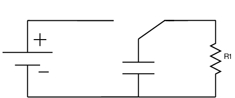
This programming lab is unlike the previous ones in that it involves circuits. Specifically it involves circuits with a battery, a capacitor and one or two resistors like the circuit you see below.
Step 1. Think about this circuit! What happens when the switch in the middle is connected to the battery? What happens when it is connected to the resistor instead?
Step 2. Here is a demo of what happens when the switch is moved to the battery and back to the resistor. Try it out! Flip the switch to the battery by pressing left arrow on the keyboard. Flip the switch back by pressing right arrow. Watch what happens to the charge on the capacitor and the current through the resistor. Feel free to flip the switch back and forth.
Step 3. In the demo, why does the charge on the capacitor instantly jump to its maximum value whenever you connect the battery? Would the charge on the capacitor change this quickly in real life? Answer these questions in 2-3 sentences in what you turn in.
Step 4. Open up the code in an editor
Click on this link to open up the code in an editor!
Important! Create an account with the editor or sign in to an existing account. Then click "Duplicate" so you can have your own version of the code!
Consider the following code from the demo:
  if ( battery_is_connected == true) {
    I = 0;
    Vcap = Vbatt;
    Q = C*Vcap;
  } else { // battery is not connected
    I = Vcap/R1;
    Q += -I*dt;
    Vcap = Q/C;
  }
Note that the current (I) in this case is the current through the resistor. The current through the resistor is zero when the switch is connected to the battery. But when the switch is moved to connect the capacitor and the resistor, there will be a current through the resistor. The only problem is that each unit of charge that leaves the capacitor to travel through the resistor will decrease the charge on the capacitor. This is why there is a minus sign in this line of code: Q += -I*dt; This makes the capacitor like a battery but with a steadily decreasing voltage. This is because the voltage across the capcitor is Q/C and if the capacitor loses charge, the voltage across it will decrease until Q is basically zero.
Step 5. Let's make the circuit more realistic like the circuit drawn below:
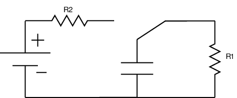
Now change the code that loads the picture of the circuit. This happens in the preload function near the beginning of the program. Just change RC.png to RC_v2.png so that the preload function looks like this:
function preload() {
  img = createImg("https://www.asc.ohio-state.edu/orban.14/RC_v2.png");
}
Run the code just to make sure that the new image shows up.
You have probably noticed that R2 is set to zero near the beginning of the code:
R1 = 5; // Ohms
R2 = 0;
We need to set R2 to some value other than zero near the beginning of the code where the variables are initialized. A good value to use is R2 = 3.
R1 = 5; // Ohms
R2 = 3;
Go ahead and make this change before moving on to the next step.
Step 6 Now we want to modify the if statement we talked about in Step 4. Change your if statement to look like the code below. Your job will be to fill in the ???
  if ( battery_is_connected == true) {
    I = ???; // current in R2, determined by Vcap, Vbatt and R2
    Q += I*dt; // charging up
    Vcap = Q/C;
  } else {  // battery is not connected
    I = Vcap/R1; // current in R1
    Q += -I*dt; // discharging
    Vcap = Q/C;
  }
Figure out what should be in the ??? in the code above! If you do this correctly, your code should behave like this
Comments:
Keep in mind that this code will be run over and over! Quantities like Q and I will change with every iteration.
The code for when the battery is connected has changed substantially. Whereas before, Vcap is just equal to the potential of the battery (Vbatt), now the code looks more like the code in the else statement except that there isn't a minus sign in this line of code: Q += I*dt;. The capacitor is charging up, instead of discharging.
The code for when the battery is connected is supposed to go like this: (1) The current in R1 is determined from the potential of the battery and the potential across the capacitor. (2) The current places more charge on the capacitor. (3) The potential across the capacitor increases because of the increased charge. Repeat!
Step 7. As you may know, the characteristic decay time of a discharging RC circuit is given by $\tau = RC$. A fimilar example is when you unplug a wireless router to reset it you are supposed to wait about 30 seconds before plugging it in again. You might think that as soon as you disconnect the power source the charge on the capacitors in the device would quickly dissipate, but what happens is a lot like the circuit shown here. Even though the battery isn't connected when the switch is thrown to the right, the charge doesn't dissipate immediately. Increase either or both the capacitance of the capacitor and the resistance of R1. Run the program to confirm that it takes longer for the charge do dissipate as expected.
Step 8 Use print("Q = ",Q); and print("I = ",I); to check if your code is giving the correct values for the max charge on the capacitor when the switch is connected to the battery. It is always important to check the results of your computer simulations to see that it gives you the answer you expect! The code for print("Q = ",Q); and print("I = ",I); is already in the code but it is commented out. All you need to do is remove the // in order to get it to work. Write down your calculation for the max charge on the capacitor and write down what it was measured to be!
Just for fun: Step 9 Wouldn't it be interesting to add an inductor to the circuit? Play around with this RLC circuit! Does the code make sense? How do the values of R, L and C affect the result? Here is a link if you just want to run the code in the browser without seeing the code
1. Comment on the demo (Step 3)
Why does the charge on the capacitor instantly jump to its max value whenever the battery is connected? Would this happen in real life? Why?
2. Modify your code as described in Step 5
Just follow the directions in Step 5. There is no guesswork here.
3. Correctly modify the if statement to calculate the current in R2 (Step 6)
The comments may help you do this. Just think of it as a homework problem. What is the current in R2 as a function of Vbat, Vcap and R2?
4. Choose larger values for C and R1 and check that it takes longer for the capacitor to discharge (Step 7)
Write down the values for C and R1 that you chose and say something like "Yes, it really did take longer" in what you turn in. You can also change R1 if you are curious. Does this affect the discharge time?
5. Quantitative number for the max charge on the capacitor (Step 8)
Write down your calculation for the max charge on the capacitor and write down what it was measured to be.