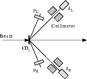
The target area (labeled (5) and (6) in fig. ![]() ) is shown in an
expanded view in figure
) is shown in an
expanded view in figure ![]() . There are three primary pieces
shown in the figure: The swinger magnets; the target and dump magnet; and
the spin precession magnets.
. There are three primary pieces
shown in the figure: The swinger magnets; the target and dump magnet; and
the spin precession magnets.

Figure: Schematic layout of the swinger and spin precession areas near the
 facility target.