As shown in figure ![]() there are really three angular cuts which
have to be made on the data:
there are really three angular cuts which
have to be made on the data:  , the sector half-angle;
  ,
the minimum polar scattering angle; and
,
the minimum polar scattering angle; and 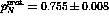 , the maximum polar
scattering angle. It has been shown in a derivation of the FOM
[Mer93] that the FOM is maximized when
, the maximum polar
scattering angle. It has been shown in a derivation of the FOM
[Mer93] that the FOM is maximized when  is a
minimum, and this is true when
is a
minimum, and this is true when  or
or
 . Further Monte Carlo studies of this estimate show
that it is valid and that the FOM is fairly insensitive to changes in the
sector half-angle [Mer93]. Therefore,
. Further Monte Carlo studies of this estimate show
that it is valid and that the FOM is fairly insensitive to changes in the
sector half-angle [Mer93]. Therefore,  is used for
all of the analysis in this thesis. A histogram showing the event
distribution in
is used for
all of the analysis in this thesis. A histogram showing the event
distribution in  for an average run is shown in figure
 ![]() .
.

Figure: Raw azimuthal  distribution of double-scattering events in
the polarimeter.
distribution of double-scattering events in
the polarimeter.  is defined as a horizontal scatter to the left.
The spikes are the result of finite size of the detector cells.
is defined as a horizontal scatter to the left.
The spikes are the result of finite size of the detector cells.
The sinusoidal nature of the  distribution that would be expected
from equation
distribution that would be expected
from equation ![]() is not obvious in figure
is not obvious in figure ![]() . In
order to show that there is an actual asymmetry in the
. In
order to show that there is an actual asymmetry in the  distribution
it is necessary to take a difference between the
distribution
it is necessary to take a difference between the  distribution when
the beam is in a
distribution when
the beam is in a  state and when it is a
  state. The
results of this subtraction can be seen in figure
state. The
results of this subtraction can be seen in figure ![]() along with
a smooth spline fit to the data which makes obvious the sinusoidal
asymmetry.
along with
a smooth spline fit to the data which makes obvious the sinusoidal
asymmetry.

Figure: Difference between the  distributions in the
  state and
the
state and
the  state for a single sample run. The dotted line is the actual
difference in the data and the solid line is a smooth spline fit to that
difference.
state for a single sample run. The dotted line is the actual
difference in the data and the solid line is a smooth spline fit to that
difference.
The polar scattering angle  window also needs to be adjusted in
order to optimize FOM. A raw
window also needs to be adjusted in
order to optimize FOM. A raw  distribution is shown in figure
![]() .
.

Figure: Raw histogram of the polar scattering angle,  ,
distribution in the polarimeter. The spikes are the result of the limited
position resolution of the detector cells.
,
distribution in the polarimeter. The spikes are the result of the limited
position resolution of the detector cells.
A lower bound, 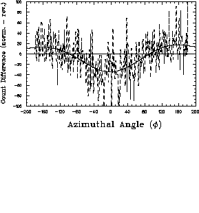 , on the polar scattering angle is used
because the events with a small
, on the polar scattering angle is used
because the events with a small  have a large uncertainty in
 . As
. As  becomes smaller the finite position resolution of
the detector cells makes it difficult to determine if a scattering took
place to the left sector or right sector. The upper bound
becomes smaller the finite position resolution of
the detector cells makes it difficult to determine if a scattering took
place to the left sector or right sector. The upper bound  on
on 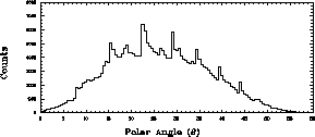 serves to cut off the point at which the analyzing power of the
reaction
serves to cut off the point at which the analyzing power of the
reaction  becomes negative. Obviously, including such
events will dilute the analyzing power of the detector and reduce the FOM.
This takes place at
becomes negative. Obviously, including such
events will dilute the analyzing power of the detector and reduce the FOM.
This takes place at  [Arn96] as shown
in figure
[Arn96] as shown
in figure ![]() .
.

Figure: Calculated values for the Analyzing Power of the
 reaction [Arn96].
In the same manner that figure ![]() shows the difference between
the
shows the difference between
the  distributions of the (+) and (-) beam states figure
![]() shows the full angular distribution of that same difference.
shows the full angular distribution of that same difference.
Figure: Full angular distribution of the difference between (+) and (-)
beam state.  is shown in the angular direction and
  in the
radial direction. Relative height indicates the event count.
in the
radial direction. Relative height indicates the event count.
The asymmetry in the distribution of scatters from the analyzer plane is very obvious.