 The basis of our experimental work in this field was the development of
 IV. B. Ion Production Environments
 The basis of our experimental work in this field was the development of
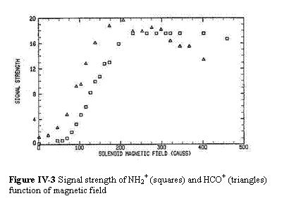
a technique for ion spectroscopythat produces signals twoorders of magnitude larger than previous techniques (367). This is especially important because prior to this development, microwave ion spectroscopy was reputed to be extremely difficult and time consuming because of the long searches for weak lines. The basis of the method is the extension of the ion rich negative glowregion of an anomalous glow discharge by means of an axial magnetic field. Inaddition to the very large gains in signal strength (~x100), the enhancement is also ion specific, thus providing a powerful discriminant. Figure IV-3 shows the observed signal as a function of applied magnetic field for two common molecular ions, HCO+ and N2H+.
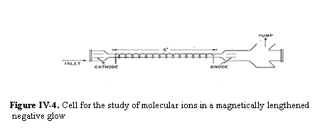
Figure IV-4 shows a particularly simple version of the magnetically lengthened negative glow cell ( 367). This cell is of all glass construction with teflon end caps. The solenoid section is immersed in liquid nitrogen. In ( 367) it was pointed out that the magnetically lengthened negative glow cell is functionally equivilant to an electron gun injecting magnetically confined electrons into a electric field free region. Based on this equivalence a new cell has been developed.
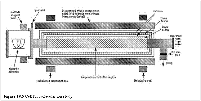
In the cell shown in Figure IV-5 the electrons are produced by a thermonic cathode and guided through a metalic tube which can be cooled either by liquid helium or liquid nitrogen. Because the requirements for sustaining an anomolous glow discharge place severe constraints on pressure, gas mixture, voltage, and current, this new cell provides significantly greater flexibility for the optimization of the production of ions. Additionally, because the parameters of the systems are much better determined, it is possible to model the ion production. This makes possible more predictive ion production schemes as well as the quantitative measurment of the physical and chemical parameters involved.
The collisions between molecular ions and neutrals at low temperature are of both fundamental and practical interest. Much of this interest in driven by the basic role these species play in the chemistry of cold molecular clouds Herbst. As a consequence, it has been one of our goals to combine the collisional cooling methodology with our magnetically enhanced molecular ion production technique to provide a general environment for a wide range of scientific studies. Figure IV-6 shows a general purpose system for the production of ions and other transient species at very low temperature in an environment suitable for quantitative collisional studies. The central region, in which the observations are made, is a collisional cooling cell with open ends for the electron beam which is generated by a heated filament and accelerator region to the left. In the collisionally
co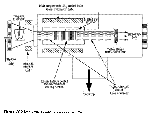 oled region, H2 is maintained between 10 - 100 K (or He between 1 - 100 K) by contact with the liquid/vapor He cooled copper walls, whose temperature is regulated by a feedback loop. In the middle of the central region, trace amounts of CO or other condensable precursor gas are continuously injected near ambient temperature into the cold H2/He buffer gas, and cooled within 10 - 100 collisions to the measured cell wall temperature. The CO or other precursor is effectively cryopumped by the helium temperature walls and has significant concentration only in the middle of the central region, as do reaction products, such as HCO+. The central helium cooled region is surrounded by a 77 K heat shield and thermally isolated at both ends from the 77 K cylindrical sections by mylar cylinders sealed with indium. The H2/He buffer gas inlet is at one end and a Teflon cap (which is transparent to the mm/submm probe) with a 1 mm diameter hole is used at the other to maintain a pressure differential between the experimental region and the
guard vacuum region.
The electron gun consists of a heated tungsten filament located in a glass appendage to the main vacuum chamber for thermal and electrical isolation. A potential of ~1 keV is maintained between the filament and the entrance to the 77 K cylinder. In addition to the axial magnetic field provided by the main solenoid, a separately adjustable magnetic field in the region of the cathode is used to optimized the trajectories of the electrons through the experimental region. In operation, electrons are produced by the heated filament, accelerated by the electric field to ~1 keV, guided to and through the collisional cooling region by the axial magnetic field, and collected in the exit 77 K region with most of their energy intact.
Because in collision experiments the kinetic temperatures of the collision partners must be well defined, careful diagnostics are required if reliable results are to be obtained. This is especially true at very low temperatures. In our earlier work on the development of the collisional cooling method, we reported diagnostic studies designed to measure and characterize the kinetic temperatures. For the study of cold ions additional factors, chiefly the open cell ends and the energy deposited by the electron beam, need to be considered. In order to understand and calibrate the kinetic temperature in the cold ion production reg ion, we developed a quantitative model of heat flow (463). This model shows that in the worst case the H2 conduction between the 77K and low temperature regions raises the temperature along the central axis a maximum of 0.5 K in the region populated by HCO+. Additionally, because
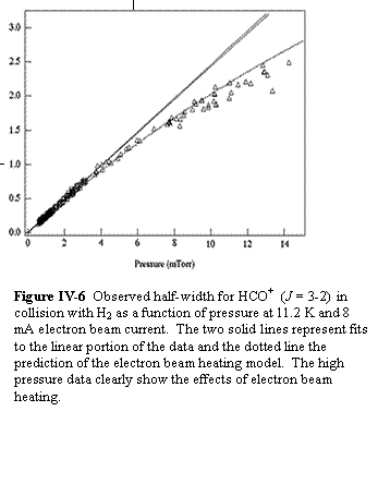 the electron beam deposits energy throughout the volume in pro
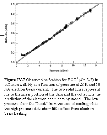 portion to current and gas density, it is possible to make comparisons between an analytic model and observations. These investigations identified large regions of pressure, temperature and current space where the electron beam has a negligible effect on measured collisional parameters. Two examples of these comparisons are shown Figure IV-6 and Figure IV-7. The range of pressures included in the fit was chosen to avoid the loss of collisional cooling efficiency at low pressure and electron beam heating at high pressure. The figures illustrate the different thermal effects nicely. Additional details of these diagnostics are given in a recent paper. (463)
| OSU Physics Department | |The College of Math and Physical Sciences | The Ohio State University |