V.C.2 The Core Spectrometer
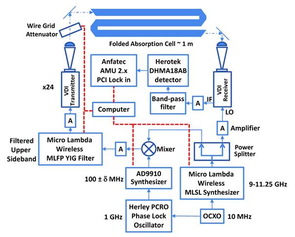
Figure V.C.2-1 shows an example of a solid state sensor system. This system is optimized for intensity calibration rather than sensitivity. In it a ×24 frequency multiplication scheme is used. Drive for this system is provided by a fast sweeping 0–400 MHz synthesizer, scanning around a nominal 100 MHz center frequency, which is subsequently mixed with a stepping synthesizer in the 8.75–11.25 GHz range to provide a tunable source offset from the receiver’s local oscillator by its intermediate frequency (IF). A YIG filter is used to select the desired sideband and suppress the many intermodulation products that grow rapidly with frequency multiplication. We will see below that the frequency stability and agility provided by this approach are very important for the speed, sensitivity, specificity, and clutter rejection of the SMM sensor.
Figure V.C. 2-1. Overview of a SMM frequency multiplication – heterodyne receiver gas sensor. In this system a frequency synthesizer near 10 GHz drives a x24 diode based frequency multiplier to provide the local oscillator of a heterodyne receiver. A sideband generation scheme provides synchronized, but offset in frequency, drive to a similar multiplier chain for probe power to the folded 1.2 m absorption cell.
Because molecular saturation often limits probe powers when sensors are operated in the low pressure Doppler limit, we chose a heterodyne detector that makes possible a system that approaches fundamental noise limits for low power probes. Since saturation is determined both by the square of the molecular dipole moment and the pressure, optimal power levels for each molecule and operating condition vary widely. In general we chose a low probe power, a few microwatts, in order to insure that under all circumstances we were in a non-saturation limit. For species with smaller dipole moments, it is possible to increase the probe power to increase sensitivity. For all species sensitivity can be improved significantly by operating at higher pressure with increased probe power. The local oscillator for this receiver is driven directly by the stepping synthesizer through a similar ×24 multiplier chain. The resulting IF signal sweeps around 2.4 GHz (100 ± δ MHz ×24) and is demodulated by a Schottky diode. An FM modulation, somewhat smaller than the Doppler linewidth, with lock-in detection was used to suppress baseline due to standing waves and other power variations. These power variations can be 5 – 10 over the 210 – 270 GHz band. Both the source and detector operate in fundamental waveguide and the power is propagated quasi-optically with horns and lenses through a 2.5 cm diameter, 1.2 m long, stainless steel folded cell. Because only a static sample of 1 – 10 mTorr is required, vacuum is provided by a small turbo and diaphragm pump combination.
[1] I.R. Medvedev, C.F. Neese, G.M. Plummer, F.C. De Lucia, Opt. Lett., 35 (2010) 1533-1535.