V.E.1 Passive terrestrial systems
V.E.1 Passive terrestrial systems
Passive imaging systems are attractive not only because they do not require an active illuminator, but also because they can produce images similar in appearance to optical photographs, without the deleterious effects of speckle and other coherent phenomena [1]. Because the thermal power grows linearly with bandwidth b, whereas the noise only grows as b1/2, the minimum detectable thermal contrast for passive imaging becomes
V.E.1-1
Consequently, it is ordinarily advantageous to choose as broad a bandwidth b as the electronics and optics of the system will allow, and a B that is as small as is consistent with frame rates, etc. With Tn= 3000 K, b = 10 GHz and B = 100 Hz, ∆Tmin = 0.3 K.
V.E.1.a Outdoors at relatively low frequency
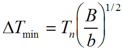
Indoors there are typically not large thermal differences across a target and signal margins can be small. As a result, many of the SMM/THz passive images take advantage of cold sky illumination out of doors. Since the atmospheric transmission to space is best at relatively low frequency, these images are often made at 94 GHz [2]. Figure V.E.1.a-1 shows one of the best known examples.
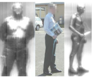
Figure V.E.1.a-1. Passive 94 GHz images with cold sky illumination (From R. Appleby).
V.E.1.b Indoors and at high frequency
With cooled bolometers that are both sensitive and which have larger optical bandwidth at higher frequencies, it is possible to build passive systems with good signal to noise. The upper panel of Fig. V.E.1.b-1 shows an image made with a cooled bolometer and several hundred GHz of bandwidth centered on 650 GHz [3]. This is a true passive image, taken indoors. It shows the differential temperature of the skin, as well as the colder glasses and hair. While this image shows the potential of passive imagers in the THz and interesting target phenomenology, it is not a practical system; being based on a 0.3 K bolometer (with an NEP ~ 4 x 10-15 W/Hz-1/2, which is near the fundamental limit) and a slow single point scanner.
Figure V.E.1.b-1. (a) An indoor image of a face made with a passive bolometer system centered on ~650 GHz and (b) an image of a face made with an active illuminator and heterodyne receiver at 632 GHz.
Several more practical imagers take advantage of low noise amplifiers at 94 GHz and line scanners to increase the allowable frame rates and integration times for indoor imaging [4]. This approach seems particularly promising as these low noise amplifiers are extended to higher frequency [5, 6], which can provide larger bandwidths, better angular resolution, and the prospect of lower cost integration.
Multiplex systems based on arrays are highly desirable in astronomy because of the cost of photons. However, large and dense heterodyne arrays are challenging to develop and most of the astronomical arrays in use are arrays of square law detectors, bolometers, photo detectors, etc. [6, 7]. However, the desirability of heterodyne arrays has caused considerable interest and effort and significant progress to this end has been made [8].
While 2-D focal plane arrays of suitable sensitivity and density have proven to be challenging, a 1 –D bolometer array has been combined with a mechanical scanner to address this issue [9]. Particular attention should be called to the innovative mechanical scanner used in this system. Another important feature of this system is that it includes an integrated cryocooler and does not require cryogens. While this is still a substantial system, it shows a development path to a useable public application.
[1] R. Appleby, R.N. Anderton, Proc. IEEE, 95 (2007) 1683-1690.
[5] L.A. Samoska, IEEE Trans. THz Sci. Tech. 1, 1 (2011) 9-24.
[7] B.S. Karasik, A.V. Sergeev, D.E. Prober, IEEE Trans. THz Sci. Tech., 1 (2011) 97-111.
[8] C.E. Groppi, J.H. Kawamura, IEEE Trans. THz Sci. Tech., 1 (2011) 85-96.
[9] E. Grossman, C. Dietlein, J. Ala-Laurinaho, M. Leivo, L. Gronberg, M. Gronholm, P. Lappalainen, A. Rautiainen, A. Tamminen, A. Luukanen, Appl. Opt., 49 (2010) E106-E120.