


December 2002 groups from Italy (Ferrara, Padova) and the US (Princeton, Ohio
State) proposed to replace the
current BaBar Resistive Plate Chambers (RPC) in the
instrumented flux return (IFR) gaps, used to detect
muons and neutral hadrons, with plastic Limited Streamer Tubes (LST).
These web pages provide more detailed information on this project as well as the
work done by the Ohio State group.
(2007 Update) This project is now complete. The last LST modules were installed during the 2006 shutdown in time for Run 6. A brief report on the LST Upgrade project can be found here.
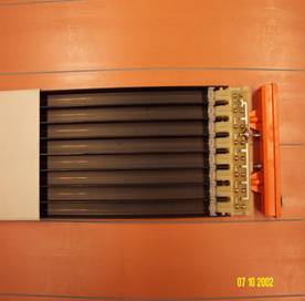
A “standard” LST cell consists of a silver plated sense wire 100 mm in diameter, located at the center of a cell of 9-mm square section. A plastic (PVC ) extruded structure, or “profile” contains 8 such cells, open on one side (fig. 2). The profile is coated with a resistive layer of graphite, having a typical surface resistivity between 0.2 and 1 MW/square. The profiles, coated with graphite and strung with wires, are inserted in plastic tubes (“sleeves”) of matching dimensions for containment of the gas mixture. Other components needed for the complete detector are end pieces with gas inlets, HV and ground connectors; spacers, which keep the wires at the centre of the cell and are installed typically every 40cm; small printed boards and their supports at the two ends of the profile for soldering the wires and providing electrical connections. If, as is likely, the dimensions of the tubes are modified, a new set of all these pieces will be designed. The signals for the measurement of one coordinate can be read directly from the wires, but it has become customary instead to read both coordinates with strip planes, thereby avoiding the complications of feed-throughs and blocking capacitors. For such tubes the operating voltage is typically 4.7kV; the plateaus are at least 200V wide; the signals on the wire are of the order of 150/200mV (over 50W), typically 50ns at the base, sometimes with an afterpulse; an average charge per pulse of 300pC can be assumed. The gas mixtures are strongly quenching: the original one (25% Ar, 75% n-pentane) being explosive has been replaced in accelerator use (SLD; ZEUS) by a non-flammable one based on CO2. The LST geometrical efficiency is limited by the plastic sides of the cells (1mm thick) and sleeves (1mm) to a worst-case value of 90%. Fortunately this effect is mitigated by the fact that most tracks area not exactly orthogonal to the profiles, and can be greatly reduced by increasing the cell size. Alternatively a double-layer geometry increases both efficiency and reliability, as long as the gap is thick enough to accommodate it.
More information on limited streamer tubes:
- Electrical Connections and Signal Path
- Anode and Cathode Signals of Large Cell Prototpyes (Part 1)
- Anode and Cathode Signals of Large Cell Prototpyes (Part 2)
- LST Test Tube: Differential Driver (on tube, 1 of 4 channels)
- LST Test Tube: Differential Receiver (in FE crate, 1 of 4 channels, no discriminator)
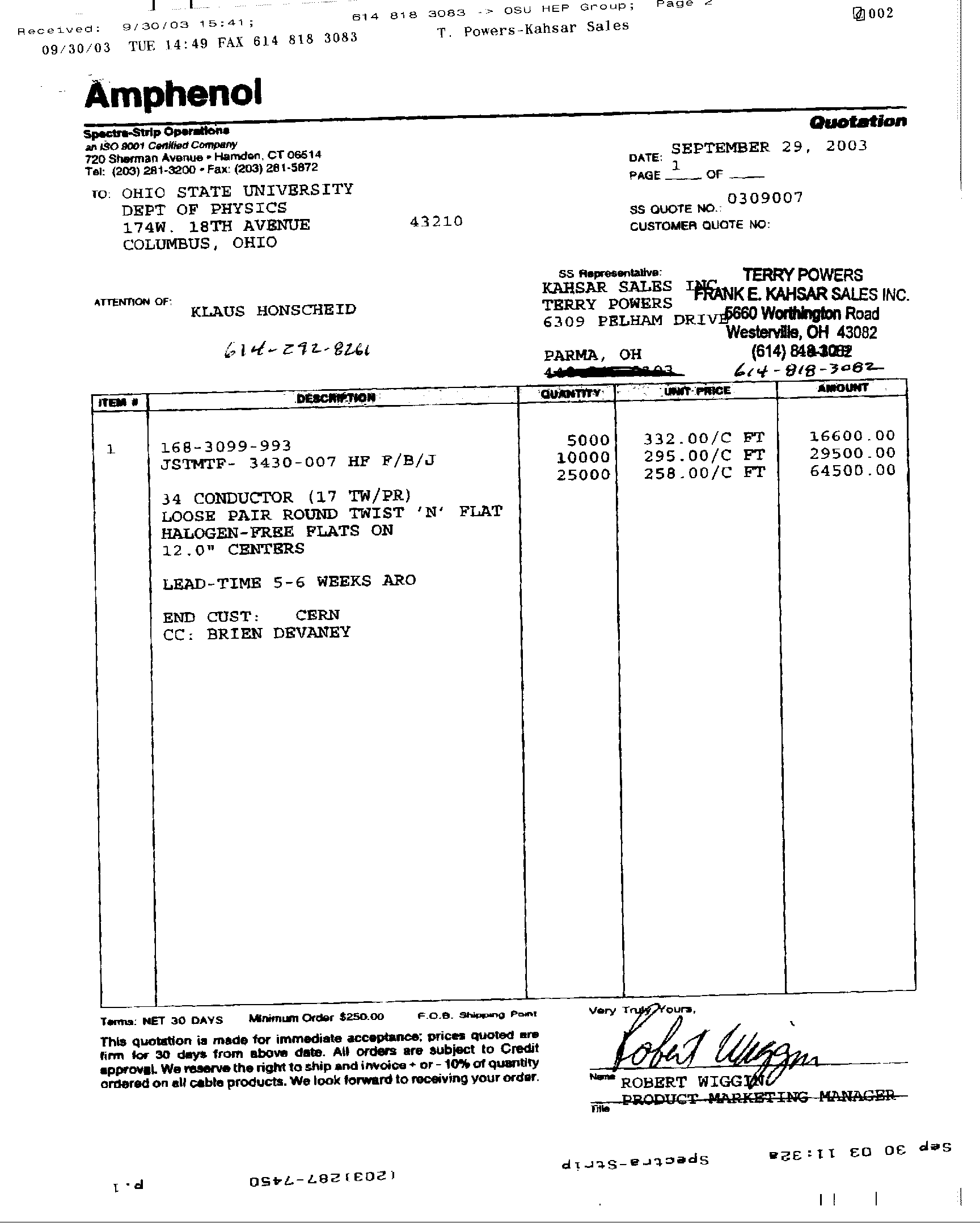
- Amphenol Signal Cable Specifications
- Amphenol Signal Cable Quote (preliminary)
- Draft of Quality Control Steps/Procedures: Module Assembly in the US
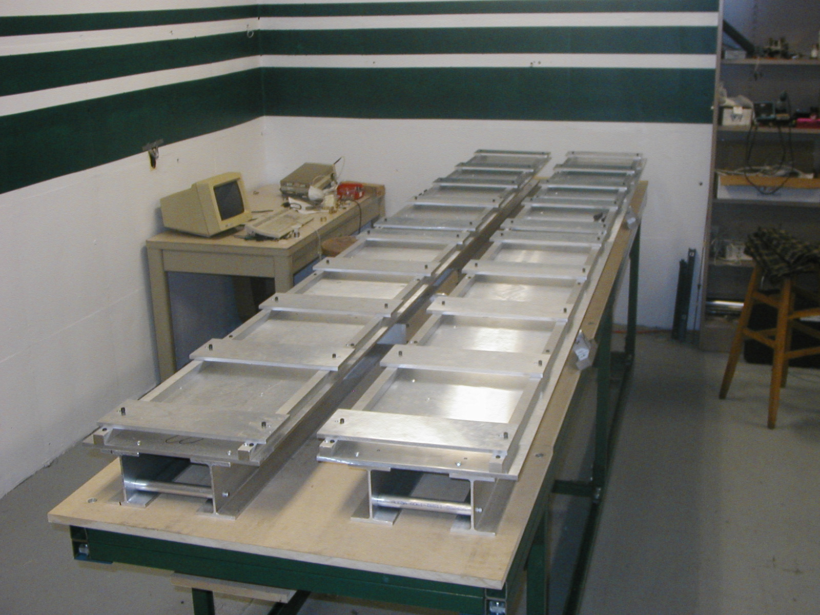
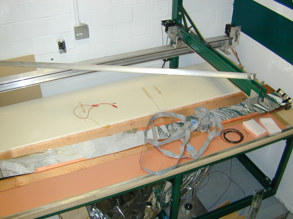
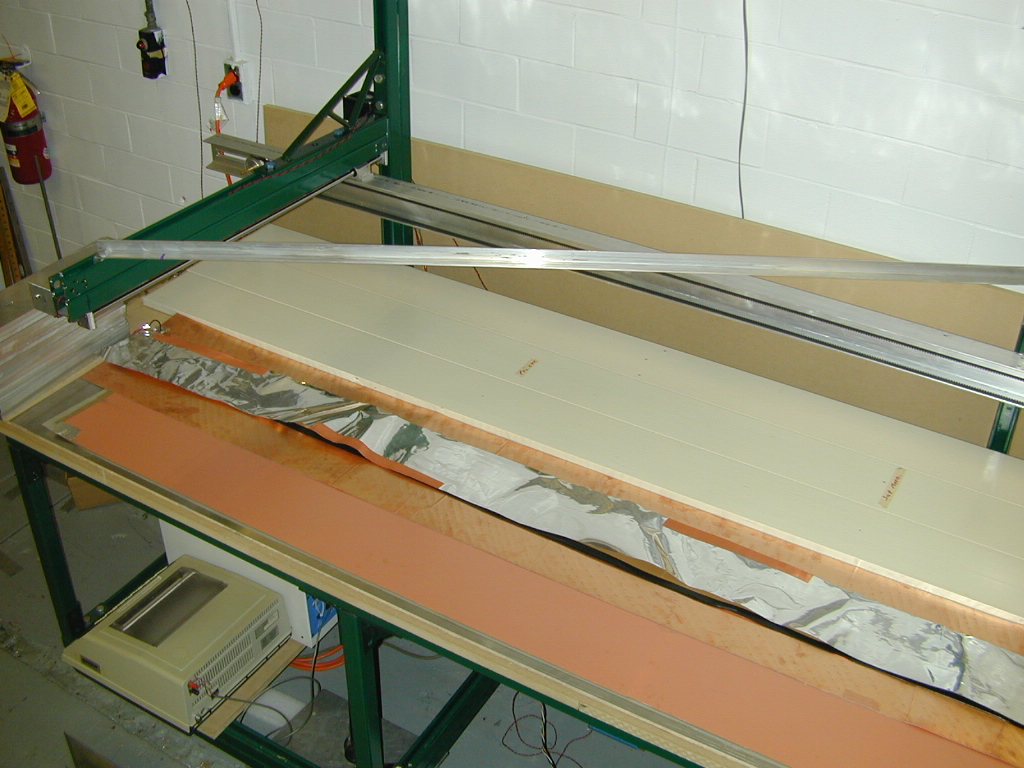
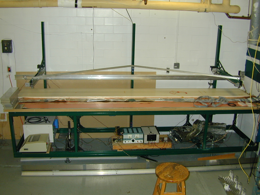
- Scan Table Design and Construction
- Scantable website
- Pictures of Source Scan Table ( 1), ( 2), ( 3)
- QC Parts and Shopping List
- Barcode Labels for the LST Detector (pdf, doc)
- Installation Manual for Intemec 1800/1802 Barcode Scanner (pdf)
- 1802 setup for the LST project
- Documentation for Qt Applications
- Draft of Quality Control Parameters for Module Assembly Sites (pdf, doc)
Mailing address Professor Klaus Honscheid
Professor Richard Kass
Dept. of Physics
The Ohio State University
174 W 18th Avenue
Columbus, OhioConference Room (614) 292-2314
Laboratories
(2029) (614 292-6799
(0180)
(VDG)Fax: (614) 292-8261